
2 layers40 × 24 mm
Nosecone
chaxaf/Supersonic-Test-Rocket
Hardware for EPFL Rocket Team Hermes Supersonic Test Rocket
20 parts

 chaxaf/Supersonic-Test-Rocket
Hardware for EPFL Rocket Team Hermes Supersonic Test Rocket
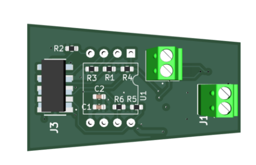
Nosecone is an open-source printed circuit board by chaxaf, from the chaxaf/Supersonic-Test-Rocket repository on GitHub. It is a 2-layer board of 36.6 × 34.6 mm with 22 parts on 16 nets, routed with 157 tracks and 28 vias.
It is built around the MAX31855KASA+. Its parts include 8 resistors, 6 capacitors, 3 ICs and 3 connectors.
Semester project completed with the EPFL Rocket Team in 2022.
Hermes II is a compact avionics architecture developed for a small experimental rocket intended for validation flights and data generation. The project focused on redesigning the electronics of the original Hermes platform into a smaller, more modular system with telemetry, GPS, multiple sensor boards, and improved integration inside the rocket.
The avionics stack is built around one main PCB and three auxiliary PCBs placed in different parts of the rocket:
The design integrates:
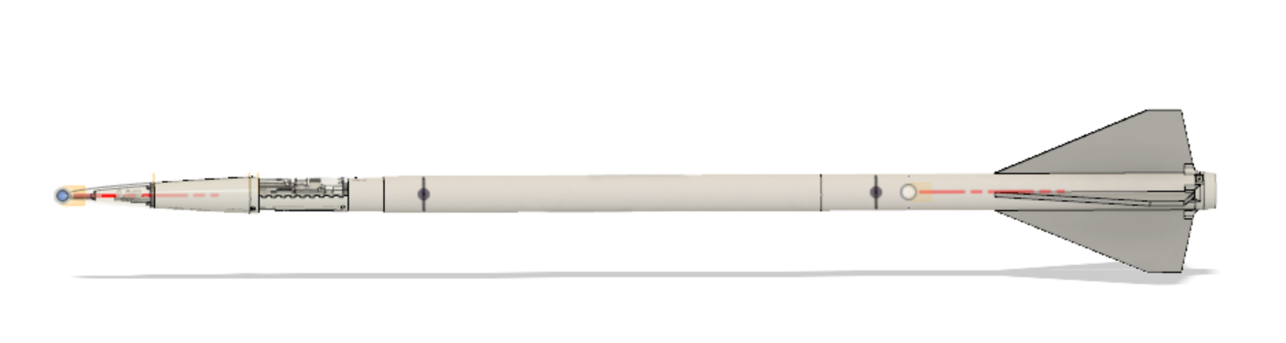
Source in repository: docs/Hermes_Presentation.pptx
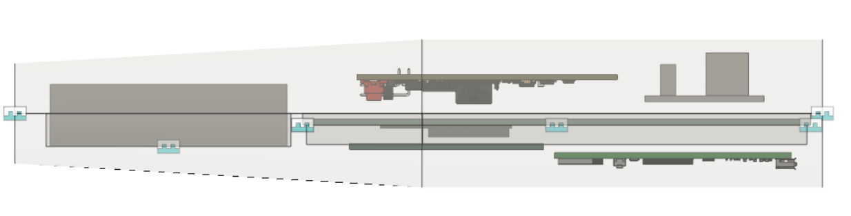
The main board had to fit inside a very constrained avionics bay while interfacing with the GPS, telemetry radio, IMU, pressure sensors, thermocouples, Altimax, Wildhorn sensor board, and auxiliary boards. It uses a 4-layer stack-up with dedicated ground and power planes.
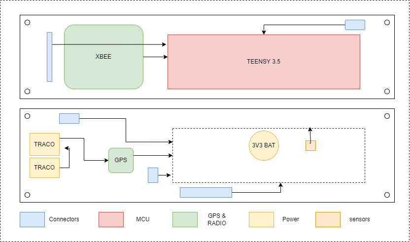
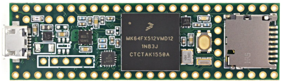
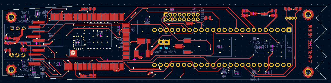
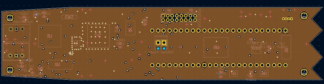
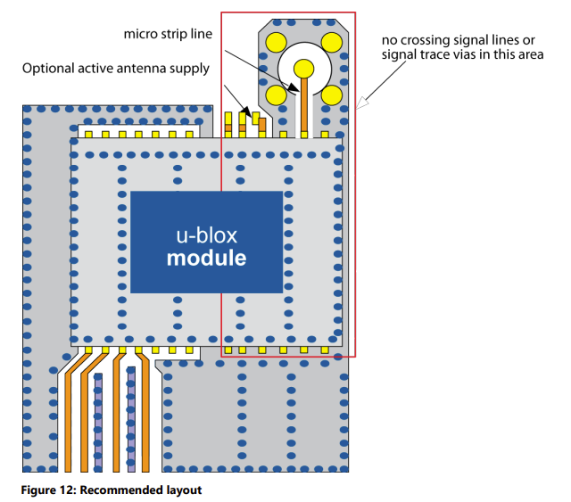
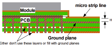
One of the most layout-sensitive parts of the board was the GPS section, especially antenna routing and the controlled-impedance microstrip connection.
Measures total pressure and wall temperature.
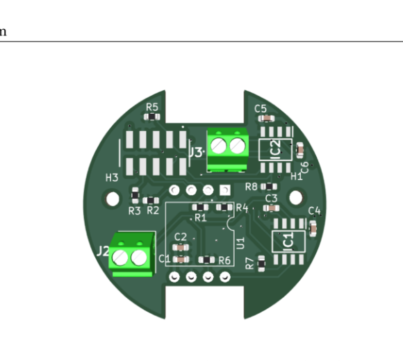
Measures static pressure and wall temperature.
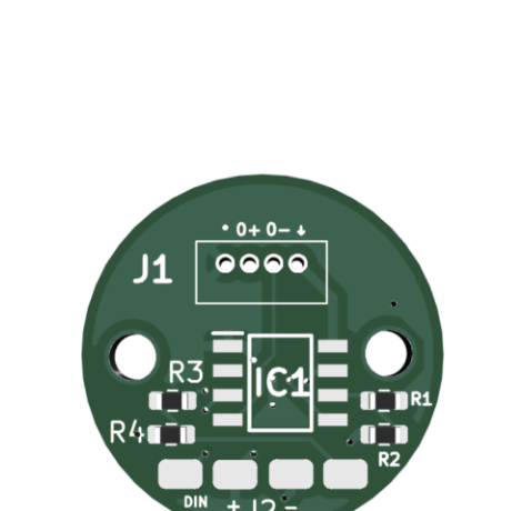
Conditions the load cell signal used for thrust measurement.
According to the final presentation, the following subsystems were functional during project testing:
Main issues and remaining work included:
See slides “RESULTATS” and “CONCLUSION” in docs/Hermes_Presentation.pptx.
Hermes-II-GitHub/
├── README.md
├── .gitignore
├── docs/
│   ├── Hermes_Presentation.pptx
│   └── report.pdf
├── images/
│   ├── rocket_overview.png
│   ├── avionics_bay.png
│   ├── system_block_diagram.png
│   ├── main_pcb_top.png
│   ├── main_pcb_bottom.png
│   ├── main_pcb_signal_routing.png
│   ├── main_pcb_power_planes.png
│   ├── gps_layout_guidelines.png
│   ├── gps_microstrip_stackup.png
│   ├── nosecone_board.png
│   ├── static_port_board.png
│   └── load_cell_board.png
└── hardware/
    ├── main_pcb/
    ├── nosecone_pcb/
    ├── static_port_pcb/
└── load_cell_pcb/The hardware design files are provided in KiCad project format. Open the corresponding .kicad_pro file in each hardware subfolder.
| Qty | Value | Footprint | References |
|---|---|---|---|
| 6 | 1kΩ | Resistor_SMD:R_0603_1608Metric | R1, R2, R3, R4, R5, R6 |
| 3 | 100nF | Capacitor_SMD:C_0603_1608Metric | C1, C4, C5 |
| 2 | 10kOhm | Resistor_SMD:R_0603_1608Metric | R7, R8 |
| 2 | 10nF | Capacitor_SMD:C_0603_1608Metric | C3, C6 |
| 2 | MAX31855KASA+ | Library:SOIC127P600X175-8N | IC1, IC2 |
| 2 | MountingHole | MountingHole:MountingHole_2.2mm_M2 | H1, H3 |
| 2 | terminal block | Library:terminal block | J1, J2 |
| 1 | 10uF | Capacitor_SMD:C_0603_1608Metric | C2 |
| 1 | B2B-PH-K-S_LF__SN_ | Library:57202G5205LF | J3 |
| 1 | RSCDJNI060PASE3 | Library:DIP-8_W13.08mm | U1 |

makingdevices/TC-Logger-Device
A thermocouple logger with USB communication


DiamondLightSource/ptRecorder
Pressure and Temperature recorder comissioned by DLS Vaccum

SomeLucky1/CoffeeHat
Basic espresso machine controls based on Arduino Nano extension board.

supermileage/telemetry-pcb
Printer Circuit Board design for Telemetry module + voltage regulators for 12v and 5v rails


ciaa/Ponchos
El poncho consta de elemento digitales y analógicos tales como: potenciómetro, buzzer, UART/RS-232, LCD 16x2, teclado matricial 4x3, y pinout para comunicaciones varias y pines de propósito general.

HasiKe/Hayabusa
Eigenbau-Motorsteuerung und Umbauprojekte für die Suzuki Hayabusa der ersten Generation (1999–2007).
It measures 36.6 × 34.6 mm and has 2 copper layers, 1.6 mm thick.
22 parts, built around the MAX31855KASA+. The full list of its parts is on this page, with links to each part's symbol and footprint where PCBKit's library has them.
From the chaxaf/Supersonic-Test-Rocket repository on GitHub, at the commit this page was made from: the board is hardware/static_port_pcb/nosecone.kicad_pcb and its schematic hardware/load_cell_pcb/load cell.kicad_sch. PCBKit opens the board in the browser, with nothing to install.
Its repository states no licence, so its author keeps all rights: ask chaxaf before reusing the design.
