
2 layers
ALU alone
ChargeInMotion/8bit-breadboard-computer
Faithful recreation of Ben Eater's 8-bit SAP-1 breadboard computer — final-year team project, breadboard to PCB.
30 partsMIT

 ChargeInMotion/8bit-breadboard-computer
Faithful recreation of Ben Eater's 8-bit SAP-1 breadboard computer — final-year team project, breadboard to PCB.
A register is an open-source printed circuit board by ChargeInMotion, from the ChargeInMotion/8bit-breadboard-computer repository on GitHub, published under the MIT licence. It is a 2-layer board with 20 parts on 29 nets, routed with 4 tracks and 0 vias.
It is built around the 74LS245SC and 74LS173SC. Its parts include 8 resistors, 8 diodes, 3 ICs and 1 capacitor.
A working 8-bit computer built from scratch, no microcontroller, no CPU chip. Just 74LS logic, three EEPROMs, and a clock, wired one gate at a time until it could run a program. Literally a charge in motion: electrons walking the bus, one pulse at a time.





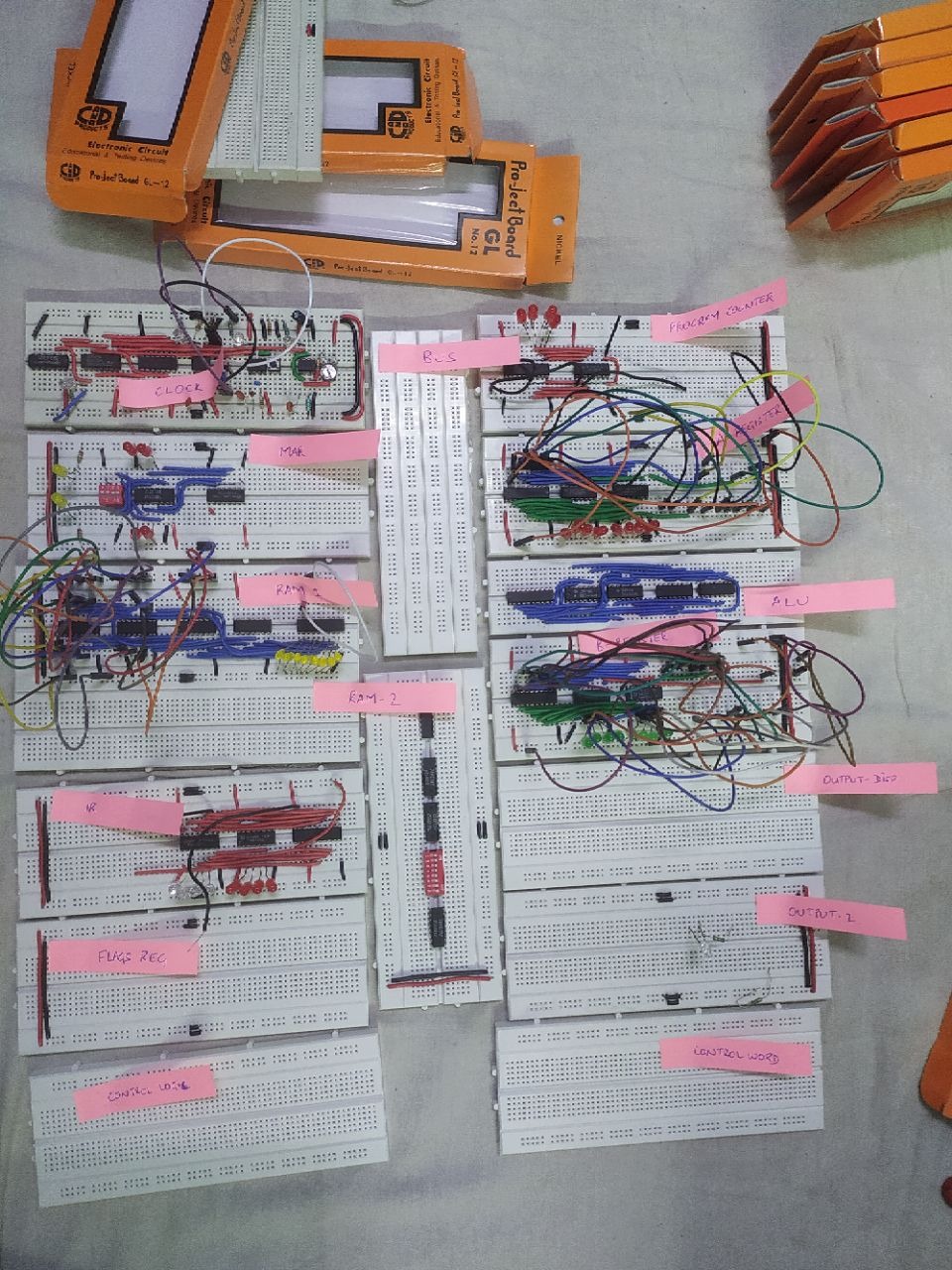
The whole machine on breadboards, every module wired and labelled by hand.
A faithful recreation of Ben Eater's 8-bit computer, the SAP-1 ("Simple As Possible") architecture from Malvino's Digital Computer Electronics, built as our final-year college project, first on breadboards and then as a soldered PCB. The goal was to understand, at the wire level, how a CPU actually works: how a clock drives a shared bus, how registers latch and release, how an ALU adds, and how a few EEPROMs become a control unit.
Credit where it's due. The design, schematics, and the superb video series are entirely Ben Eater's work (eater.net/8bit, YouTube). This repo documents our build of it. No design changes, we followed the reference faithfully and learned every module by reproducing it.
Built by three of us, final year, always & forever, the people you build your first computer with.
"You have my sword." "And my bow." "And my axe.", three of us, one bus, one fellowship that saw it through to the PCB.
Our aim was simple to say and hard to do: build and understand the working of an actual 8-bit computer on a breadboard, putting four years of ECE, every analog and digital fundamental we'd been taught, to work on one bench. A CPU had always been a black box that just "executes instructions"; the only way to truly open it is to build one by hand, place every gate, route every bus line, and watch a program move through it one clock pulse at a time. Where our own coursework left gaps, Ben Eater's series filled them.
We followed it end to end, breadboard first, then PCB. You don't skip steps: you earn each module by getting the one before it to actually work.
"It is not our abilities that show what we truly are. It is our choices.", and we chose to do it the hard way, with discrete logic.
LDA 14, ADD 15, OUT, load a value, add another, show the
sum on the 7-segment display.Every module hangs off one common 8-bit bus. The control logic decides, each clock step, which module drives the bus and which latches from it.
                          ┌──────────────── 8-BIT BUS ────────────────┐
                          │     │      │       │      │      │        │
                    ┌─────┴─┐ ┌─┴───┐ ┌┴─────┐ ┌┴───┐ ┌┴────┐ ┌──────┴─┐
        Clock ────▶ │ Prog. │ │ MAR │ │ RAM  │ │ IR │ │  A  │ │ Output │
        module      │ Count │ │     │ │16×8  │ │    │ │ reg │ │ reg +  │
          │         └───────┘ └─────┘ └──────┘ └─┬──┘ └──┬──┘ │ 7-seg  │
          │                                      │       │    └────────┘
          │                              ┌───────┘   ┌───┴───┐
          ▼                              ▼           ▼       ▼
   ┌──────────────┐                 ┌─────────┐   ┌──────┐ ┌──────┐
   │ Control Unit │◀── opcode ──────│ Instr.  │   │  B   │ │ ALU  │
   │ (3× EEPROM   │── control sigs ─│ decoder │   │ reg  │▶│ Σ /  │
   │  microcode)  │   to all modules└─────────┘   └──────┘ │ A−B  │
   └──────────────┘                                        └──────┘
Modules: clock · program counter · memory address register (MAR) · RAM · instruction register · A & B registers · ALU (adder/subtractor) · output register (7-segment) · CPU control logic.
Control logic. The instruction register's upper nibble is the opcode; the
lower nibble is the operand. 28C16 EEPROMs hold the microcode lookup tables,
for each opcode, a sequence of up to 5 micro-steps asserting control signals like
CO (counter out), MI (MAR in), RO (RAM out), AI (A in), EO (ALU out),
SU (subtract), OI (output in), J (jump), HLT (halt).
We built and verified each unit on its own before wiring it to the bus, you don't get to the Mines of Moria without first learning to read the map.
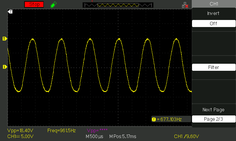
Every good build has a boss fight. Ours was the 555-timer clock, right at the start, and nothing else in the machine works until the clock does. Every great scheme needs the clock to strike on time.
No 1.21 gigawatts needed, just one capacitor in the right place. Great Scott, the clock was clean. A small fix that teaches why every real board is littered with decoupling caps.
The full parts list from Eater's reference build (~$250–300, 14 breadboards), which we followed:
| Category | Parts |
|---|---|
| Clock | 4× 555 timer |
| Logic, gates | 2× 74LS00 (NAND) · 1× 74LS02 (NOR) · 5× 74LS04 (inverter) · 3× 74LS08 (AND) · 1× 74LS32 (OR) · 2× 74LS86 (XOR) |
| Flip-flops / registers | 1× 74LS107 (dual JK) · 8× 74LS173 (4-bit D register) · 1× 74LS273 (octal D flip-flop) |
| Counters | 2× 74LS161 (4-bit synchronous counter) |
| Decoders | 1× 74LS138 (3-to-8) · 1× 74LS139 (dual 2-to-4) |
| Data path | 4× 74LS157 (2-to-1 mux) · 6× 74LS245 (octal bus transceiver) · 2× 74LS283 (4-bit adder) |
| Memory | 2× 74189 (64-bit RAM) · 3× 28C16 EEPROM (microcode) |
| Display / input | 4× common-cathode 7-segment · 8-pos + 4-pos DIP switches · 3× toggle · 3× tact switches |
| Indicators | 44× red, 12× green, 8× yellow, 21× blue LEDs |
| Passives | resistors (1k/10k/100k/470/1M) · 1MΩ pot · caps (0.01/0.1/1µF, plus rail decoupling) · 22 AWG wire |
| Build surface | 14× breadboards → soldered PCB |
Sourcing. Every IC, breadboard, jumper, wire, and tool was bought in person from the Chandni Chowk electronics market in Delhi, half the adventure was hunting down each 74LS part across the lanes.
printf, you debug with a meter, a
logic probe, and the clock single-stepped by hand.Beyond the write-up above, this repo holds the actual artifacts from our build:
design/kicad-8bit-computer/: our KiCad capture of the full computer (clock,
program counter, MAR, RAM, instruction register, A and B registers, ALU, output,
control logic) plus the custom footprints we drew.design/pcb-modules/: the per-module boards we laid out in KiCad, A register,
B register, ALU, control logic, instruction register, program counter.simulation/A_register.pdsprj: a Proteus simulation of the register before we
committed it to copper.images/scope/: oscilloscope captures from the running machine.docs/8bit-alu-thesis-redacted.pdf: our project report. Personal contact
details and roll numbers are removed.Open the .sch and .kicad_pcb files in KiCad to view or edit the design.
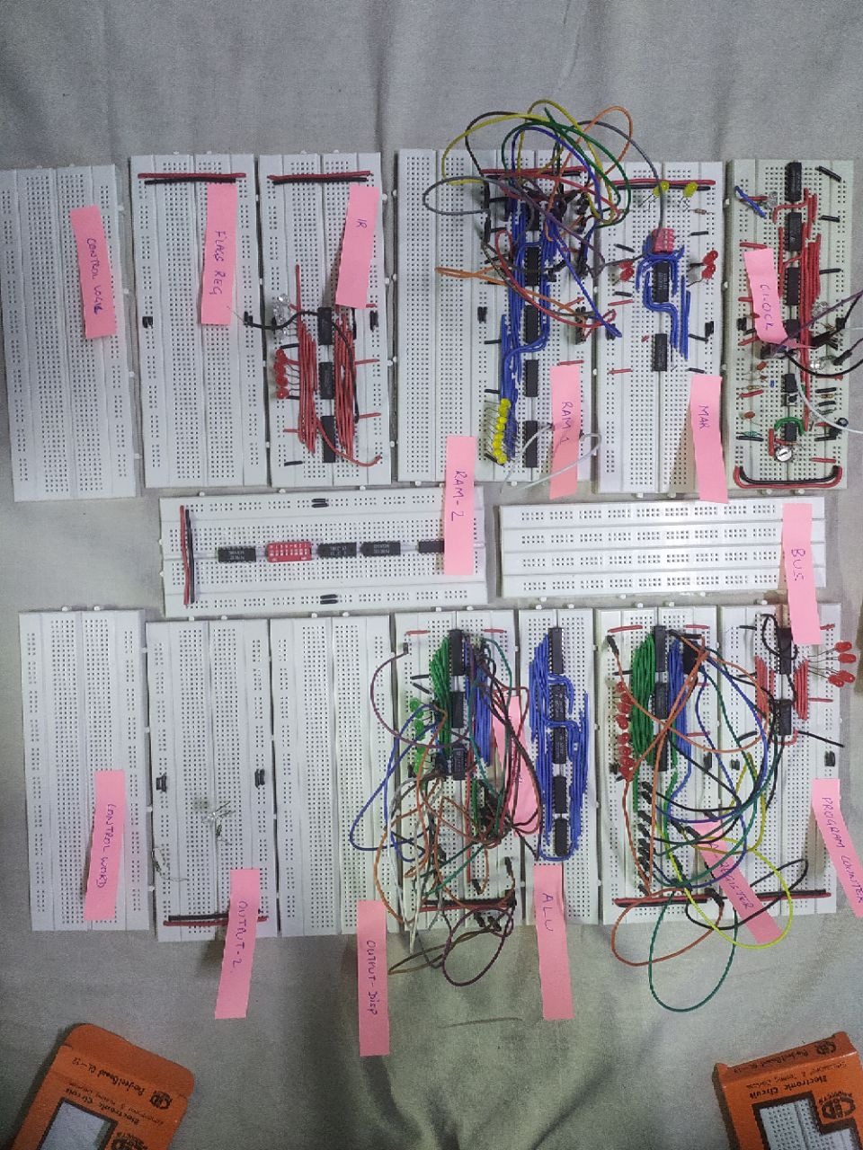
The breadboard build, the bus running down the middle with each module hung off it:
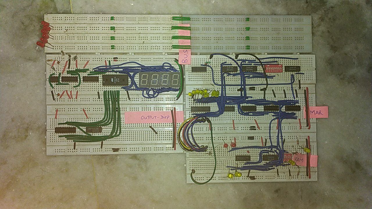
The output stage: a 7-segment display decoded off the bus, next to the MAR and RAM.
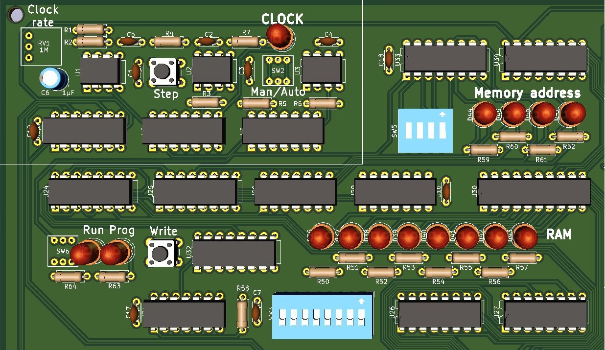
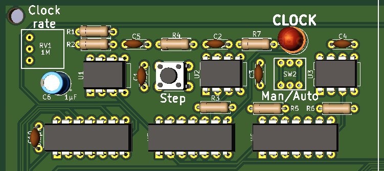
After the breadboard worked end to end, we laid it out as a PCB. KiCad 3D views:
The 555 clock running at about 961 Hz on a Siglent scope, after the decoupling fix described above. Clean square edges, stable supply.
A faithful recreation today; ideas for later, roughly increasing in difficulty:
LDA/ADD/OUT demoAll design credit belongs to Ben Eater. This repository is our hands-on build and notes, shared in the same spirit of learning his series is taught in.
Sarosh (KJ) · github.com/ChargeInMotion · sarosh@chargeinmotion.dev "I'm a charge in motion."
| Qty | Value | Footprint | References |
|---|---|---|---|
| 8 | 220 | Resistor_THT:R_Axial_DIN0516_L15.5mm_D5.0mm_P5.08mm_Vertical | R24, R25, R26, R27, R28, R29, R30, R31 |
| 8 | RED | LED_THT:LED_D3.0mm | D10, D11, D12, D13, D14, D15, D16, D17 |
| 2 | 74LS173 | Package_DIP:DIP-16_W7.62mm_Socket | U8, U9 |
| 1 | 0.1uF | Capacitor_THT:C_Disc_D3.0mm_W1.6mm_P2.50mm | C11 |
| 1 | 74LS245 | Package_DIP:DIP-20_W7.62mm_Socket | U7 |
20 parts, built around the 74LS245SC and 74LS173SC. The full list of its parts is on this page, with links to each part's symbol and footprint where PCBKit's library has them.
From the ChargeInMotion/8bit-breadboard-computer repository on GitHub, at the commit this page was made from: the board is design/pcb-modules/A_register/A_register.kicad_pcb. PCBKit opens the board in the browser, with nothing to install.
Its repository publishes it under the MIT licence: you may reuse it on that licence's terms (keep the author's notice, and for a copyleft licence share your changes alike).
ChargeInMotion/8bit-breadboard-computer
Faithful recreation of Ben Eater's 8-bit SAP-1 breadboard computer — final-year team project, breadboard to PCB.

ChargeInMotion/8bit-breadboard-computer
Faithful recreation of Ben Eater's 8-bit SAP-1 breadboard computer — final-year team project, breadboard to PCB.

The-Invent0r/8-bit-Computer-PCB
These are the KiCAD files for my 8-Bit Computer.


rraider/Seminarkurs2021
Entwicklung eines turingvollständigen, primitiven Microcontroller in der Software Digital

Trilobyte-CPU/8-bit-computer
A DIY 8-bit computer built mostly with discrete logic chips


