
2 layers166 × 137.7 mm
Receiver
charbel-j-estephan/Fm_Stereo_Encoder_Decoder
FM stereo encoder and decoder with 19 kHz pilot, designed in LTspice and KiCad.
165 parts
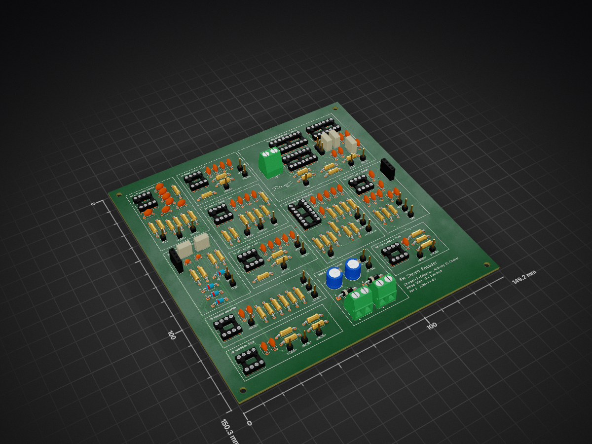
FM stereo encoder and decoder with 19 kHz pilot, designed in LTspice and KiCad.
Encoder is an open-source printed circuit board by charbel-j-estephan, from the charbel-j-estephan/Fm_Stereo_Encoder_Decoder repository on GitHub. It is a 2-layer board of 149.1 × 150.3 mm with 170 parts on 98 nets, routed with 962 tracks and 6 vias.
It is built around the MC1496D, TL072 and NE5532, with the CD4013, CD4046BE and CD4069 among its other parts. Its parts include 55 resistors, 52 capacitors, 12 ICs, 6 diodes and 5 connectors.


The final version is Encoder. Open Encoder.kicad_pro in KiCad 10. It holds the schematic (Encoder.kicad_sch) and the board (Encoder.kicad_pcb). Use these two files for printing and for building.
This board is the encoder half of the FM stereo project. It takes the left and right audio from the J3 input and turns them into one stereo multiplex (MPX) signal on the J4 output. The output feeds the FM transmitter module.
The board does these jobs.
JP1 flips the carrier phase. If left and right come out swapped at the receiver, move the JP1 shunt to the other position. No reprint is needed.
| Qty | Value | Footprint | References |
|---|---|---|---|
| 28 | 100n | Capacitor_THT:C_Disc_D5.0mm_W2.5mm_P5.00mm | C10, C13, C14, C15, C16, C18, C19, C21, C22, C27, C28, C29, C30, C37, C38, C39 +12 |
| 13 | 100k | Resistor_THT:R_Axial_DIN0207_L6.3mm_D2.5mm_P10.16mm_Horizontal | R4, R6, R19, R20, R21, R22, R23, R24, R25, R26, R27, R28, R30 |
| 10 | TestPoint | Connector_PinHeader_2.54mm:PinHeader_1x01_P2.54mm_Vertical | TP_-9V1, TP_+9V1, TP_GND1, TP_GND2, TP_GND3, TP_GND4, TP_GND5, TP_L1, TP_L2, TP_R1 |
| 8 | 10k | Resistor_THT:R_Axial_DIN0207_L6.3mm_D2.5mm_P10.16mm_Horizontal | R2, R3, R9, R10, R11, R12, R38, R52 |
| 6 | TL072 | Package_DIP:DIP-8_W7.62mm_Socket | U1, U3, U4, U5, U6, U8 |
| 5 | 12k | Resistor_THT:R_Axial_DIN0207_L6.3mm_D2.5mm_P10.16mm_Horizontal | R13, R14, R15, R17, R51 |
| 5 | 1u | Capacitor_THT:C_Rect_L7.2mm_W3.5mm_P5.00mm | C1, C2, C45, C46, C49 |
| 4 | 1 n | Capacitor_THT:C_Disc_D5.0mm_W2.5mm_P5.00mm | C23, C24, C25, C26 |
| 4 | 100K | Resistor_THT:R_Axial_DIN0207_L6.3mm_D2.5mm_P10.16mm_Horizontal | R45, R48, R49, R50 |
| 4 | 15k | Resistor_THT:R_Axial_DIN0207_L6.3mm_D2.5mm_P10.16mm_Horizontal | R39, R40, R43, R44 |
| 4 | 1N4148 | Diode_THT:D_DO-35_SOD27_P7.62mm_Horizontal | D3, D4, D5, D6 |
| 4 | GND | Connector_PinHeader_2.54mm:PinHeader_1x01_P2.54mm_Vertical | TP30, TP31, TP32, TP35 |
| 4 | M3 | MountingHole:MountingHole_3.2mm_M3 | H1, H2, H3, H4 |
| 3 | 1k | Resistor_THT:R_Axial_DIN0207_L6.3mm_D2.5mm_P10.16mm_Horizontal | R29, R35, R37 |
| 3 | 1n | Capacitor_THT:C_Disc_D5.0mm_W2.5mm_P5.00mm | C5, C20, C47 |
| 2 | 1.8k | Resistor_THT:R_Axial_DIN0207_L6.3mm_D2.5mm_P10.16mm_Horizontal | R7, R8 |
| 2 | 100p | Capacitor_THT:C_Disc_D3.0mm_W2.0mm_P2.50mm | C11, C12 |
| 2 | 1N5819 | Diode_THT:D_DO-41_SOD81_P10.16mm_Horizontal | D1, D2 |
| 2 | 2.2 n | Capacitor_THT:C_Disc_D5.0mm_W2.5mm_P5.00mm | C32, C34 |
| 2 | 2.4k | Resistor_THT:R_Axial_DIN0207_L6.3mm_D2.5mm_P10.16mm_Horizontal | R1, R5 |
| 2 | 22u | Capacitor_THT:CP_Radial_D8.0mm_P3.50mm | C3, C4 |
| 2 | 3.3k | Resistor_THT:R_Axial_DIN0207_L6.3mm_D2.5mm_P10.16mm_Horizontal | R16, R18 |
| 2 | 3.9k | Resistor_THT:R_Axial_DIN0207_L6.3mm_D2.5mm_P10.16mm_Horizontal | R34, R36 |
| 2 | 330 p | Capacitor_THT:C_Disc_D5.0mm_W2.5mm_P5.00mm | C31, C33 |
| 2 | 51 | Resistor_THT:R_Axial_DIN0207_L6.3mm_D2.5mm_P10.16mm_Horizontal | R31, R32 |
| 2 | Conn_01x02_Socket | TerminalBlock_Phoenix:TerminalBlock_Phoenix_MKDS-1,5-2-5.08_1x02_P5.08mm_Horizontal | J1, J2 |
| 2 | Conn_01x04_Socket | Connector_PinSocket_2.54mm:PinSocket_1x04_P2.54mm_Vertical | J3, J4 |
| 2 | NE5532 | Package_DIP:DIP-8_W7.62mm_Socket | U2, U10 |
| 1 | 1.2n | Capacitor_THT:C_Disc_D5.0mm_W2.5mm_P5.00mm | C6 |
| 1 | 1.5k | Resistor_THT:R_Axial_DIN0207_L6.3mm_D2.5mm_P10.16mm_Horizontal | R55 |
| 1 | 19K_DIV | Connector_PinHeader_2.54mm:PinHeader_1x01_P2.54mm_Vertical | TP34 |
| 1 | 19K_IN | Connector_PinHeader_2.54mm:PinHeader_1x01_P2.54mm_Vertical | TP11 |
| 1 | 19K_IN_Terminal | TerminalBlock_Phoenix:TerminalBlock_Phoenix_MKDS-1,5-2-5.08_1x02_P5.08mm_Horizontal | J5 |
| 1 | 2.2k | Resistor_THT:R_Axial_DIN0207_L6.3mm_D2.5mm_P10.16mm_Horizontal | R42 |
| 1 | 2.2n | Capacitor_THT:C_Disc_D5.0mm_W2.5mm_P5.00mm | C17 |
| 1 | 220P | Capacitor_THT:C_Disc_D5.0mm_W2.5mm_P5.00mm | C36 |
| 1 | 270K | Resistor_THT:R_Axial_DIN0207_L6.3mm_D2.5mm_P10.16mm_Horizontal | R46 |
| 1 | 3.3n | Capacitor_THT:C_Disc_D5.0mm_W2.5mm_P5.00mm | C35 |
| 1 | 360K | Resistor_THT:R_Axial_DIN0207_L6.3mm_D2.5mm_P10.16mm_Horizontal | R47 |
| 1 | 38K_IN | Connector_PinHeader_2.54mm:PinHeader_1x01_P2.54mm_Vertical | TP12 |
| 1 | 38K_VCO | Connector_PinHeader_2.54mm:PinHeader_1x01_P2.54mm_Vertical | TP33 |
| 1 | 4.7k | Resistor_THT:R_Axial_DIN0207_L6.3mm_D2.5mm_P10.16mm_Horizontal | R53 |
| 1 | 6.8k | Resistor_THT:R_Axial_DIN0207_L6.3mm_D2.5mm_P10.16mm_Horizontal | R33 |
| 1 | 7.5k | Resistor_THT:R_Axial_DIN0207_L6.3mm_D2.5mm_P10.16mm_Horizontal | R41 |
| 1 | 8.2k | Resistor_THT:R_Axial_DIN0207_L6.3mm_D2.5mm_P10.16mm_Horizontal | R54 |
| 1 | CD4013 | Package_DIP:DIP-14_W7.62mm_Socket | U12 |
| 1 | CD4046 | Package_DIP:DIP-16_W7.62mm_Socket | U11 |
| 1 | CD4069 | Package_DIP:DIP-14_W7.62mm_Socket | U13 |
| 1 | MC1496 | Package_DIP:DIP-14_W7.62mm_Socket | U9 |
| 1 | MOD_OUT_N | Connector_PinHeader_2.54mm:PinHeader_1x01_P2.54mm_Vertical | TP23 |
| 1 | MOD_OUT_P | Connector_PinHeader_2.54mm:PinHeader_1x01_P2.54mm_Vertical | TP22 |
| 1 | OUT | Connector_PinHeader_2.54mm:PinHeader_1x01_P2.54mm_Vertical | TP29 |
| 1 | SWAP_LR | Connector_PinHeader_2.54mm:PinHeader_1x03_P2.54mm_Vertical | JP1 |
| 1 | U10A_OUT | Connector_PinHeader_2.54mm:PinHeader_1x01_P2.54mm_Vertical | TP24 |
| 1 | U10B_OUT | Connector_PinHeader_2.54mm:PinHeader_1x01_P2.54mm_Vertical | TP25 |
| 1 | U1A_OUT | Connector_PinHeader_2.54mm:PinHeader_1x01_P2.54mm_Vertical | TP13 |
| 1 | U1B_OUT | Connector_PinHeader_2.54mm:PinHeader_1x01_P2.54mm_Vertical | TP15 |
| 1 | U2A_OUT | Connector_PinHeader_2.54mm:PinHeader_1x01_P2.54mm_Vertical | TP28 |
| 1 | U3A_OUT | Connector_PinHeader_2.54mm:PinHeader_1x01_P2.54mm_Vertical | TP14 |
| 1 | U3B_OUT | Connector_PinHeader_2.54mm:PinHeader_1x01_P2.54mm_Vertical | TP16 |
| 1 | U4A_OUT | Connector_PinHeader_2.54mm:PinHeader_1x01_P2.54mm_Vertical | TP17 |
| 1 | U5A_OUT | Connector_PinHeader_2.54mm:PinHeader_1x01_P2.54mm_Vertical | TP18 |
| 1 | U5B_OUT | Connector_PinHeader_2.54mm:PinHeader_1x01_P2.54mm_Vertical | TP19 |
| 1 | U6A_OUT | Connector_PinHeader_2.54mm:PinHeader_1x01_P2.54mm_Vertical | TP20 |
| 1 | U6B_OUT | Connector_PinHeader_2.54mm:PinHeader_1x01_P2.54mm_Vertical | TP21 |
| 1 | U8A_OUT | Connector_PinHeader_2.54mm:PinHeader_1x01_P2.54mm_Vertical | TP26 |
| 1 | U8B_OUT | Connector_PinHeader_2.54mm:PinHeader_1x01_P2.54mm_Vertical | TP27 |
charbel-j-estephan/Fm_Stereo_Encoder_Decoder
FM stereo encoder and decoder with 19 kHz pilot, designed in LTspice and KiCad.


MR-DOS/guitar_down_octave
A octave-down effect for guitar. All analog, no microcontroller, no DSP.


mzuelch/CATs-Eurosynth
Analog Synth Eurorack Modules


cyberboy666/_transcribe_
midi to rs232 bridge - for performance control of old video mixers and switchers

Aykut-Gencer-KARACA/RS-36512VDC3A-MotorDriver-Hbridge
Bu proje, bir önceki çalışmamda kullandığım RS-365 serisi 12 V DC / 3 A motoru çift yönlü ve hız kontrollü sürmek için tasarlanmış bir H-köprü kartıdır.

Shrijal2410/BionicArm
Our project aims to provide a realistic, functional prosthetic hand for those who have lost theirs. We're not delving into mastering neurology; instead, we're focusing on using muscle sensor data (EMG) to control the…
It measures 149.1 × 150.3 mm and has 2 copper layers, 1.6 mm thick.
170 parts, built around the MC1496D, TL072, NE5532 and CD4013. The full list of its parts is on this page, with links to each part's symbol and footprint where PCBKit's library has them.
From the charbel-j-estephan/Fm_Stereo_Encoder_Decoder repository on GitHub, at the commit this page was made from: the board is Encoder/Encoder.kicad_pcb and its schematic Decoder/Receiver.kicad_sch. PCBKit opens the board in the browser, with nothing to install.
Its repository states no licence, so its author keeps all rights: ask charbel-j-estephan before reusing the design.