
2 layers70.1 × 43.2 mm
Iaq device
nkitanov/iaq_board
IAQ Board is a DIY (Do-It-Yourself) device for measuring internal air quality
19 parts396

 chaitya37/bme280-i2c-breakout
KiCad breakout board for the bosch BME280 sensor. I2C interface with onboard pullups and decoupling- ready to plug any microcontroller project
Bme280 sensor is an open-source printed circuit board by chaitya37, from the chaitya37/bme280-i2c-breakout repository on GitHub. It is a 2-layer board of 14.5 × 13.5 mm with 5 parts on 4 nets, routed with 63 tracks and 4 vias.
It is built around the BME280. Its parts include 2 resistors, 1 capacitor, 1 IC and 1 connector. It belongs with the sensors and measurement and interfaces and adapters boards of this library.
A minimal, ready-to-use I2C breakout board for the Bosch BME280 temperature/humidity/pressure sensor. Designed in KiCad — exposes a clean 4-pin interface (VCC, GND, SDA, SCL) for easy connection to any microcontroller.
| Parameter | Value |
|---|---|
| Input | 3.3V |
| Interface | I2C |
| I2C address | 0x76 (SDO tied to GND) |
| Current draw | <1mA typical |
| PCB | 2-layer |
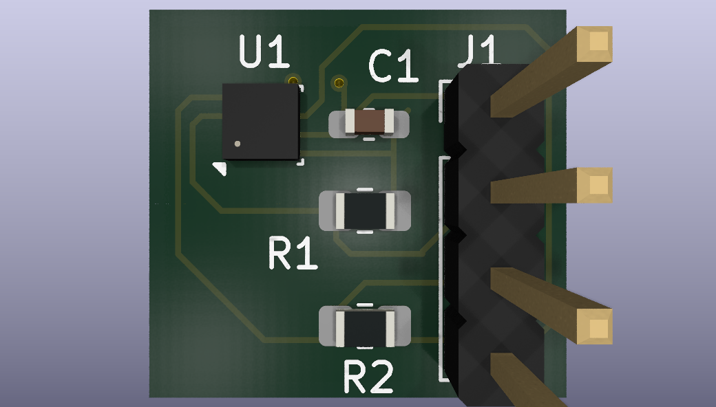
See schematic.pdf for the full schematic.
Full BOM: Bme280 sensor.csv
| Ref | Component | Value/Part | Footprint |
|---|---|---|---|
| U1 | Sensor | BME280 | Bosch_LGA-8_2.5x2.5mm_P0.65mm |
| R1, R2 | Resistor | 4.7kΩ | R_0805_2012Metric |
| C1 | Capacitor | 100nF | C_0603_1608Metric |
| J1 | Pin Header | 1x4, 2.54mm | PinHeader_1x04_P2.54mm_Vertical |
Note: the BME280 ships in an LGA-8 package (2.5x2.5mm, 0.65mm pitch) — hand-soldering this without hot air rework or a reflow setup is very difficult. Recommended: use JLCPCB/PCBWay's assembly service to have the sensor placed and reflowed for you.
Bme280 sensor.kicad_sch — KiCad schematic sourceBme280 sensor.kicad_pcb — KiCad PCB sourceschematic.pdf — Exported schematicgerber.zip — Fabrication-ready Gerber files (JLCPCB/PCBWay compatible)drill.zip — Drill filesBme280 sensor.csv — Bill of materialsDesigned and DRC-clean (0 violations, 0 unconnected nets). Boards ordered for fabrication — photos and test results to be added once assembled.
MIT — feel free to use, modify, or build on this design.
| Qty | Value | Footprint | References |
|---|---|---|---|
| 2 | 4.7k | Resistor_SMD:R_0805_2012Metric_Pad1.20x1.40mm_HandSolder | R1, R2 |
| 1 | 100n | Capacitor_SMD:C_0603_1608Metric_Pad1.08x0.95mm_HandSolder | C1 |
| 1 | BME280 | Package_LGA:Bosch_LGA-8_2.5x2.5mm_P0.65mm_ClockwisePinNumbering | U1 |
| 1 | Conn_01x04_Pin | Connector_PinHeader_2.54mm:PinHeader_1x04_P2.54mm_Vertical | J1 |
It measures 14.5 × 13.5 mm and has 2 copper layers, 1.6 mm thick.
5 parts, built around the BME280. The full list of its parts is on this page, with links to each part's symbol and footprint where PCBKit's library has them.
From the chaitya37/bme280-i2c-breakout repository on GitHub, at the commit this page was made from: the board is Bme280 sensor.kicad_pcb and its schematic Bme280 sensor.kicad_sch. PCBKit opens the board in the browser, with nothing to install.
Its repository states no licence, so its author keeps all rights: ask chaitya37 before reusing the design.
nkitanov/iaq_board
IAQ Board is a DIY (Do-It-Yourself) device for measuring internal air quality


New-England-Weather-Balloon-Society/Tiny4FSK
Horus Binary v2 HAB Tracker


kbx81/ClimateSprinklerController
ESP32-based climate and sprinkler controller for use with ESPHome

crnicholson/StratoSoar-MK3
StratoSoar MK3, an autonomous glider meant for high-altitudes, accessible to everyone


CCHS-Melbourne/ESPlant
Environmental Sensor Plant - solar WiFi gardening/meteorological sensor using ESP8266