
2 layers56.6 × 57.7 mm
Dreamcast VGA Adapter
nunosousa/DC_VGA_Adapter
This is a project detailing a Dreamcast VGA circuit adapter to provide VGA video output.
41 parts

 cepetr/sio2flip13
Flipper Zero application that emulates SIO peripherals for Atari 8-bit computers.
Sio2flip is an open-source printed circuit board by cepetr, from the cepetr/sio2flip repository on GitHub, published under the GPL-3.0 licence. It is a 2-layer board of 64 × 12 mm with 11 parts on 13 nets, routed with 45 tracks and 13 vias.
It is built around the 74HCT2G34GW. Its parts include 7 connectors, 2 resistors, 1 capacitor and 1 IC. It belongs with the retro computing and games boards of this library.
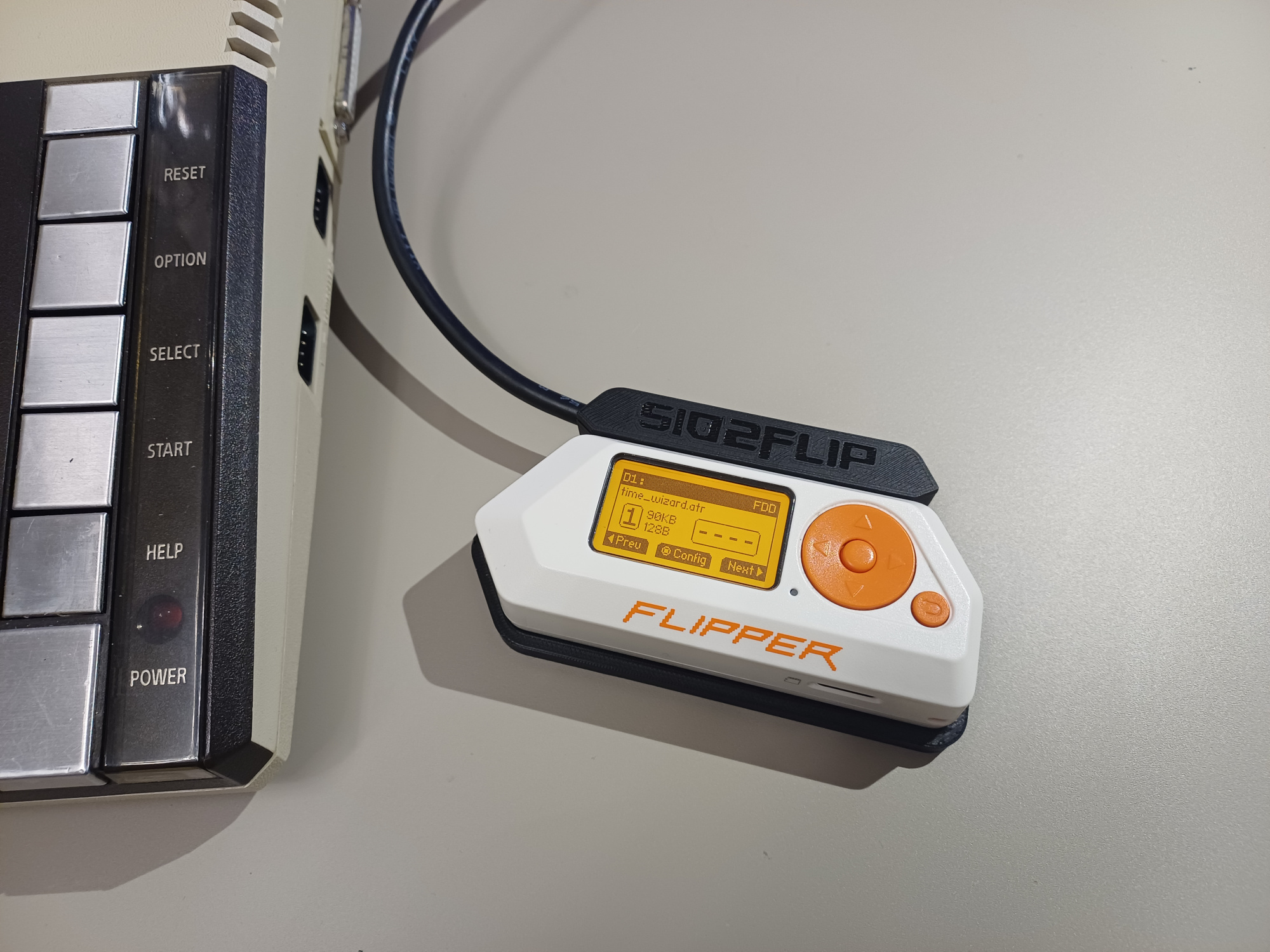
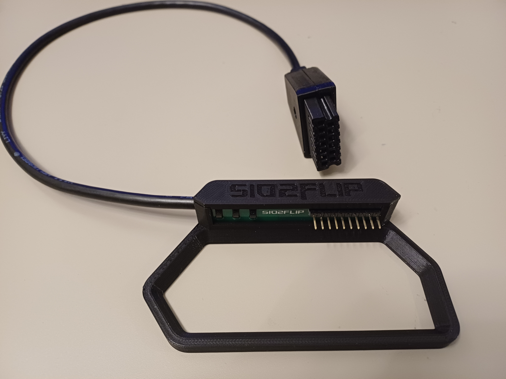
SIO2FLIP is a Flipper Zero application that emulates SIO peripherals for Atari 8-bit computers. The project is still in its early stages, but it already features:
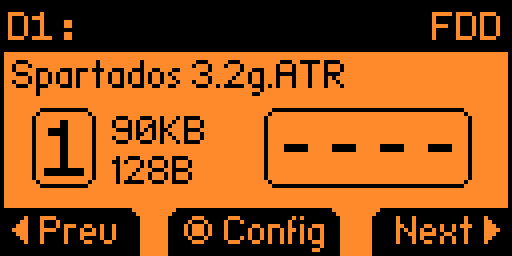
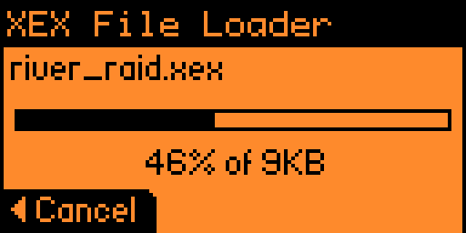
The wiring is quite simple; only three signals are need.
| Flipper pin | Atari SIO |
|---|---|
| TX (13) | DIN |
| RX (14) | DOUT |
| C0 (16) | COMMAND |
| GND (18) | GND |
Note: All signals on the Atari SIO use 5V TTL logic. Although the Flipper Zero’s I/Os are 5V tolerant when configured as inputs, be careful when connecting your Flipper Zero to your Atari computer, as incorrect wiring or improper use could potentially damage your Flipper or your precious Atari hardware.
Or you can build something more reliable - docking station ↗.
The emulator supports ATR disk images and XEX executables. To use them, copy the files to the SD card as follows:
For Atari 850 emulation, you need to provide the Atari 850 ROM file. Copy the ROM content to:
Note: I cannot include the ROM file with the app, so you’ll need to provide it yourself. The file must be exactly 4 KB in size and have the following SHA-256 checksum: 5c490a04d9936a87d3f9b6919ddaccbde30e3fb37f03a7557695d0c33f47bb8a.
You can use the excellent 80-column Ice-T terminal, available on the AtariAge forum. There you’ll also find there a link to ready-to-run ATR images that include everything you need.
Steps:
Enable Atari 850 emulation from the sio2flip main menu and select Start emulation…
Boot an ATR image containing DOS, RS232.COM, and ICET.COM (Hold the OPTION key during boot to disable the built-in BASIC ROM)
Load and run RS232.COM. This will download the R: driver from the emulator and install it.
Load and run ICET.COM.
Connect your Flipper Zero via USB. Two virtual COM ports will appear:
Run the bridge.py script from this repository:
python3 bridge.py <sio_vcp> <server>There are several great SIO peripheral emulators available, many more advanced than this project. However, none run on the Flipper Zero - so I built this purely for enjoyment. 😄
Contributions, ideas, feedback, and bug reports are welcome!
Planned improvements (time permitting):
| Qty | Value | Footprint | References |
|---|---|---|---|
| 6 | Conn_01x01_Pin | Library:SolderWirePad_1x01_SMD_2x2mm | J2, J3, J4, J5, J6, J7 |
| 1 | 10k | Resistor_SMD:R_0805_2012Metric | R2 |
| 1 | 1u | Capacitor_SMD:C_0805_2012Metric | C1 |
| 1 | 22 | Resistor_SMD:R_0805_2012Metric | R1 |
| 1 | 74HCT2G34 | Package_TO_SOT_SMD:SOT-23-6 | U1 |
| 1 | Conn_01x10 | Connector_PinHeader_2.54mm:PinHeader_1x10_P2.54mm_Vertical | J1 |
nunosousa/DC_VGA_Adapter
This is a project detailing a Dreamcast VGA circuit adapter to provide VGA video output.

google/mozc-devices
Circuit diagrams and firmware source code for Gboard DIY keyboards


FrameworkComputer/ExpansionCards
Reference designs and documentation to create Expansion Cards for the Framework Laptop

hoglet67/RGBtoHDMI
Bare-metal Raspberry Pi project that provides pixel-perfect sampling of Retro Computer RGB/YUV video and conversion to HDMI

hackclub/OnBoard
💡 Join 1,000 teenagers and make your first PCB with a $100 grant!


tardate/LittleArduinoProjects
a collection of "Little Electronic & Arduino Projects", most involving electronics or an Arduino in one way or another!
It measures 64 × 12 mm and has 2 copper layers, 1.6 mm thick.
11 parts, built around the 74HCT2G34GW. The full list of its parts is on this page, with links to each part's symbol and footprint where PCBKit's library has them.
From the cepetr/sio2flip repository on GitHub, at the commit this page was made from: the board is hardware/kicad/sio2flip.kicad_pcb and its schematic hardware/kicad/sio2flip.kicad_sch. PCBKit opens the board in the browser, with nothing to install.
Its repository publishes it under the GPL-3.0 licence: you may reuse it on that licence's terms (keep the author's notice, and for a copyleft licence share your changes alike).