4 layers57 × 22.5 mm
NB3 hindbrain
NoBlackBoxes/LastBlackBox
A course for brains interested in brains (not tools interested in tools)
147 parts69

 CentyLab/RotoPD_Pro13
Repo for RotoPD Pro hardware and documentation
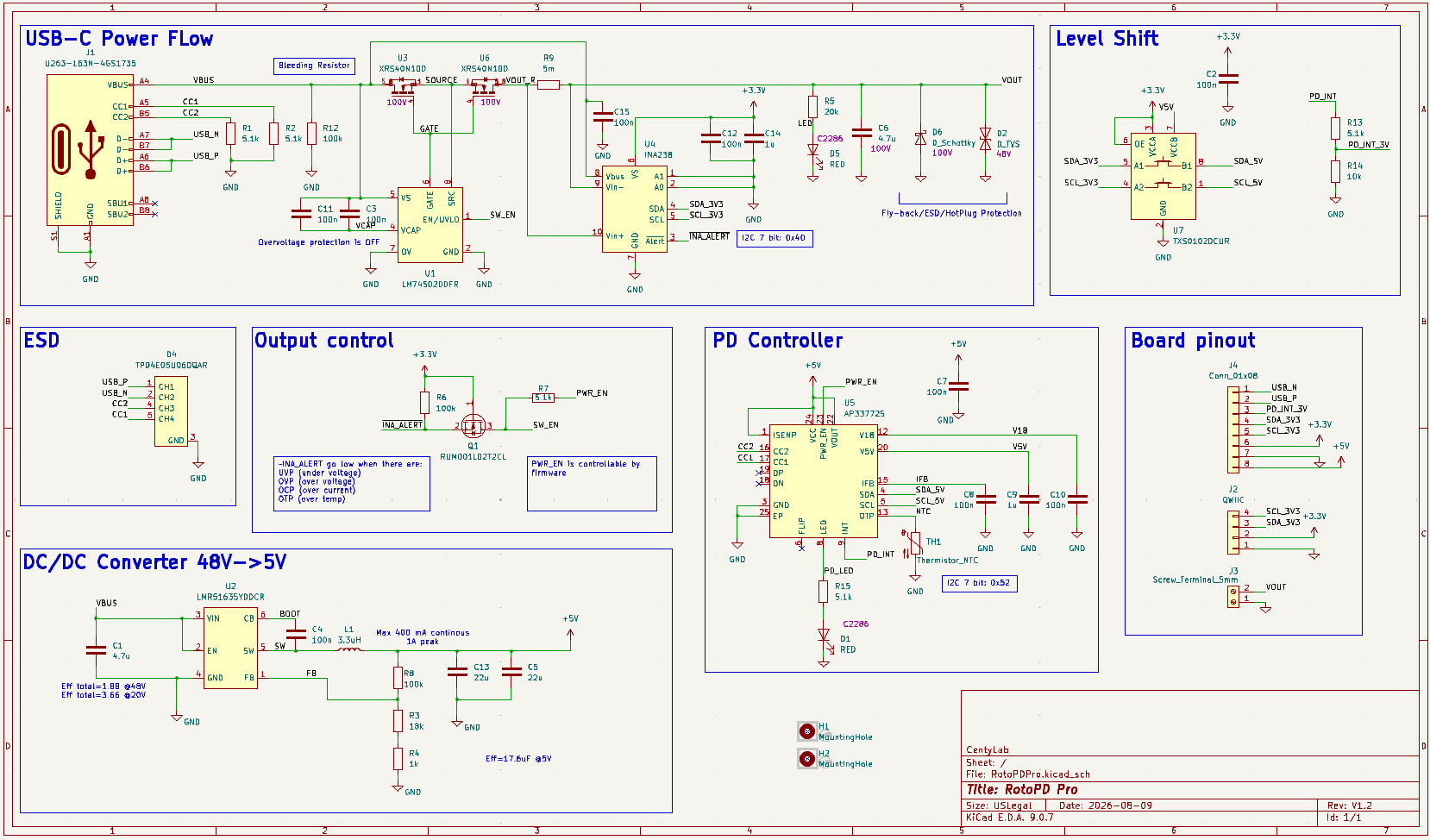
RotoPD Pro is an open-source printed circuit board by CentyLab, from the CentyLab/RotoPD_Pro repository on GitHub. It is a 2-layer board of 24.4 × 35.8 mm with 50 parts on 40 nets, routed with 404 tracks and 103 vias.
It is built around the XRS40N10D, TXS0102DCUR and RUM001L02T2CL, with the TPD4E05U06DQAR and U263-163N-4GS1735 among its other parts. Its parts include 15 capacitors, 13 resistors, 7 ICs, 5 diodes and 4 connectors.


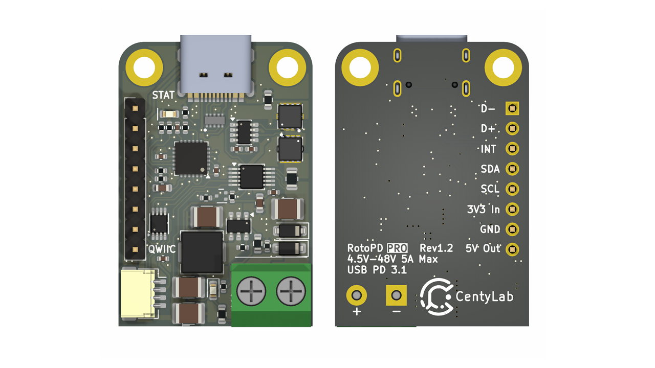
You can install the libraries directly on ArduinoIDE. Library version 1.1.0 and later will support RotoPD Pro
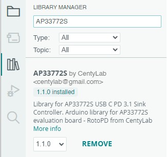
While traditional power adapters can provide a variety of current but fixed to 5V output, our RotoPD Pro leverages advanced power delivery protocols to achieve a versatile output range — 4.5V to 48V at 240W max. The breakout board use a stand alone Power Delivery Sink controller to negotiate with your modern charger and provide different output voltage.
Centylab's RotoPD Pro can unlock more advance mode in your USB-C power supplies like Programmable Power Supply (PPS) and Adjustable Voltage Supply (AVS), to provide even more granular voltage adjustment. The RotoPD Pro simplifies power negotiation with USB-C adapters, handling the complex process of establishing power delivery contracts. The controller does all the heavy lifting of power negotiation and provides an easy way to configure over I2C, free your micro-controller from the complicated USB-C PD protocol.
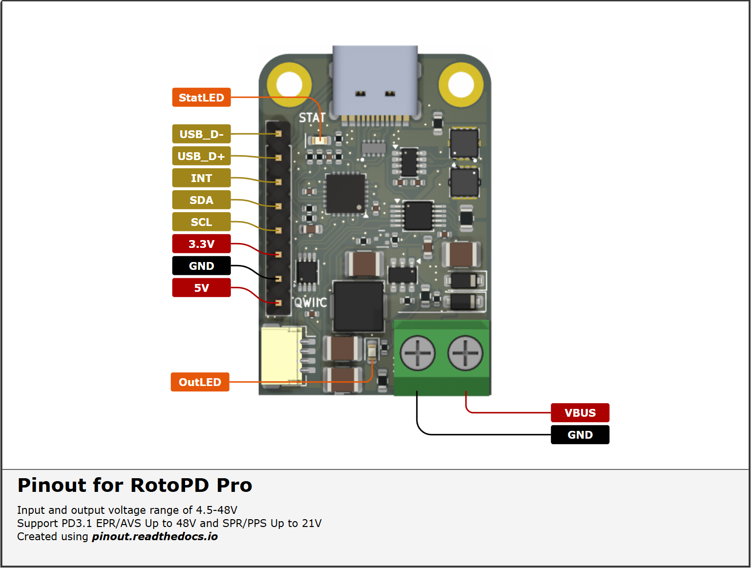
To config the board, you will need an I2C bus. The board integrates seamlessly into the Qwiic and STEMMA QT ecosystems, no soldering is required. Unlike the previous version, the board only work with 3.3V I2C logic voltage.
To make it even easier to use, RotoPD Pro includes a built-in buck converter that efficiently steps down USB-C VBUS power to a stable 5V output, making it perfect for powering microcontrollers, sensors, and other low-voltage components in your project.
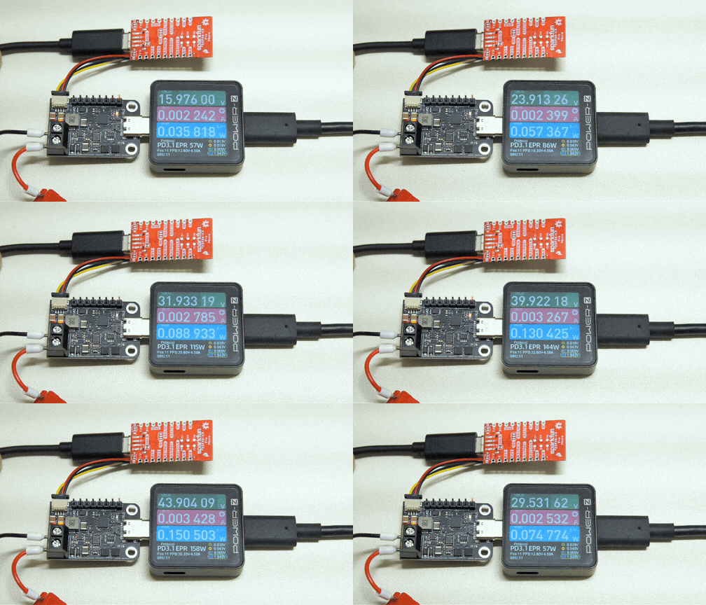
To ultilize AVS power profile, you will need a powerbank or charger that has AVS profile and a 240W USB-C cable. Here are some chargers that we found support AVS profile.
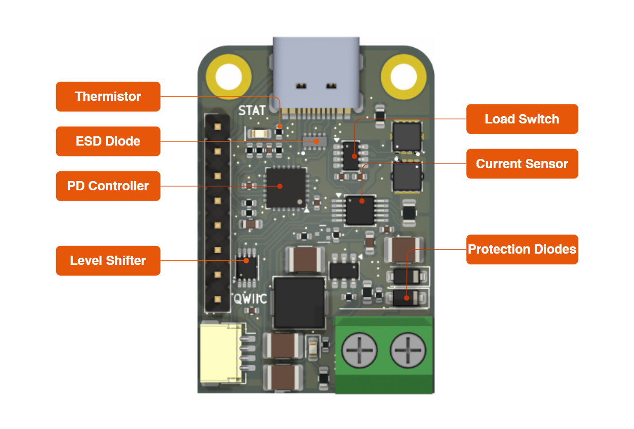
AVSCycle example with Sparkfun Pro Micro ESP32-C3. We are requesting AVS profile from 15V to 48V.
| Qty | Value | Footprint | References |
|---|---|---|---|
| 8 | 100n | Capacitor_SMD:C_0402_1005Metric | C2, C3, C7, C8, C10, C11, C12, C15 |
| 5 | 5.1k | Resistor_SMD:R_0402_1005Metric | R1, R2, R7, R13, R15 |
| 2 | 100k | Resistor_SMD:R_0402_1005Metric | R6, R8 |
| 2 | 1u | Capacitor_SMD:C_0603_1608Metric | C9, C14 |
| 2 | 22u | Capacitor_SMD:C_1210_3225Metric | C5, C13 |
| 2 | 4.7u | Capacitor_SMD:C_1210_3225Metric | C1, C6 |
| 2 | MountingHole | MountingHole:MountingHole_2.7mm_M2.5_DIN965_Pad_TopBottom | H1, H2 |
| 2 | RED | LED_SMD:LED_0603_1608Metric | D1, D5 |
| 2 | XRS40N10D | Transistor_MOSFET:DFN-8(3.3x3.3) | U3, U6 |
| 1 | 100k | Resistor_SMD:R_0603_1608Metric | R12 |
| 1 | 100n | Resistor_SMD:R_0402_1005Metric | C4 |
| 1 | 10k | Resistor_SMD:R_0402_1005Metric | R14 |
| 1 | 18k | Resistor_SMD:R_0603_1608Metric | R3 |
| 1 | 1k | Resistor_SMD:R_0402_1005Metric | R4 |
| 1 | 20k | Resistor_SMD:R_0603_1608Metric | R5 |
| 1 | 3.3uH | Inductor_SMD:L_APV_APH0530 | L1 |
| 1 | 5m | Resistor_SMD:R_0805_2012Metric | R9 |
| 1 | AP33772S | Interface_USBC:QFN-24-1EP_4x4mm_P0.5mm_EP2.6x2.6mm | U5 |
| 1 | Conn_01x08 | Connector_PinHeader_2.54mm:PinHeader_1x08_P2.54mm_Vertical | J4 |
| 1 | D_Schottky | Diode_SMD:D_SOD-123 | D6 |
| 1 | D_TVS | Diode_SMD:D_SOD-123F | D2 |
| 1 | INA238 | Package_SO:VSSOP-10_3x3mm_P0.5mm | U4 |
| 1 | LM74502DDFR | Package_TO_SOT_SMD:TSOT-23-8 | U1 |
| 1 | LMR51635YDDCR | Package_TO_SOT_SMD:TSOT-23-6 | U2 |
| 1 | LOGO | Logo:CentyLab_logo | G*** |
| 1 | QWIIC | Connector_JST:JST_SH_SM04B-SRSS-TB_1x04-1MP_P1.00mm_Horizontal | J2 |
| 1 | RUM001L02T2CL | Package_TO_SOT_SMD:SOT-723 | Q1 |
| 1 | Screw_Terminal_5mm | TerminalBlock_Phoenix:TerminalBlock_Phoenix_MKDS-1,5-2_1x02_P5.00mm_Horizontal | J3 |
| 1 | TPD4E05U06DQAR | Diode_TVS:SON50P100X255X50-10N | D4 |
| 1 | TXS0102DCUR | Package_SO:VSSOP-8_2.3x2mm_P0.5mm | U7 |
| 1 | Thermistor_NTC | Resistor_SMD:R_0402_1005Metric | TH1 |
| 1 | U263-163N-4GS1735 | Connector_USBC:USB_C_GSwitch | J1 |
It measures 24.4 × 35.8 mm and has 2 copper layers, 1.6 mm thick.
50 parts, built around the XRS40N10D, TXS0102DCUR, RUM001L02T2CL and TPD4E05U06DQAR. The full list of its parts is on this page, with links to each part's symbol and footprint where PCBKit's library has them.
From the CentyLab/RotoPD_Pro repository on GitHub, at the commit this page was made from: the board is Hardware/RotoPDPro.kicad_pcb and its schematic Hardware/RotoPDPro.kicad_sch. PCBKit opens the board in the browser, with nothing to install.
Its repository states no licence, so its author keeps all rights: ask CentyLab before reusing the design.
NoBlackBoxes/LastBlackBox
A course for brains interested in brains (not tools interested in tools)

mbabela/secured-vehicle-monitoring
Repository for my bachelor thesis at FEEC BUT

ThomasStolt/LongTermEnvLogger
The aim of this project is to measure, store, display and evaluate the temperature in the rooms of a large building over an extended time period. This project has 2 main components:


BerkeleyLab/Marble
Dual FMC FPGA carrier board developed for general purpose use in particle accelerator electronics instrumentation.

ts-manuel/iMX6-Demo-Board
Demo board for the i.MX6ULL Single-Core Processor with Arm Cortex-A7 Core

