2 layers103 × 30.5 mm

 cellularmitosis/TTLSerialOptoisolator
A board which provides isolation for a TTL serial TX / RX pair.
TTLSerialOptoisolator is an open-source printed circuit board by cellularmitosis, from the cellularmitosis/TTLSerialOptoisolator repository on GitHub, published under the MIT licence. It is a 2-layer board of 30.5 × 12.1 mm with 9 parts on 10 nets, routed with 46 tracks and 0 vias.
Its parts include 4 resistors, 2 ICs and 2 connectors. It belongs with the interfaces and adapters boards of this library.
A board which provides isolation for a TTL serial TX / RX pair.
This board design is Open-Source Hardware. It is licensed under the MIT License. It was designed by Jason Pepas.
Initial board design.
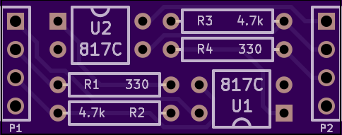
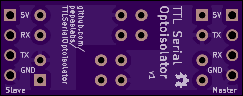
PDF.
Can we find an LED resistor value which works for both 3.3V and 5V TTL levels?
Lite-On LTV-817 datasheet: http://media.digikey.com/pdf/Data%20Sheets/Lite-On%20PDFs/LTV-817_827_847%28M,S,S_TA1%29.pdf
The forward voltage of the LED is typically 1.2V.
| Voltage | 100Ω | 150Ω | 220Ω | 330Ω | 470Ω | 680Ω | 1kΩ |
|---|---|---|---|---|---|---|---|
| 5V | 38mA | 25mA | 17mA | 12mA | 8mA | 6mA | 4mA |
| 3.3V | 21mA | 14mA | 10mA | 6mA | 4mA | 3mA | 2mA |
So 330Ω would be a reasonable choice.
| Qty | Value | Footprint | References |
|---|---|---|---|
| 2 | 330 | R_AXIAL_0W25_059A_PL | R1, R4 |
| 2 | 4.7k | R_AXIAL_0W25_059A_PL | R2, R3 |
| 2 | 817C | DIP4_059A_PL | U1, U2 |
| 2 | CONN_4 | PIN_ARRAY_4x1 | P1, P2 |
| 1 | OSHW-logo_silkscreen-back_2mm | OSHW-logo_silkscreen-back_2mm | G*** |


FrameworkComputer/ExpansionCards
Reference designs and documentation to create Expansion Cards for the Framework Laptop

VoronDesign/Voron-Hardware
Cool Hardware designed by the Voron Design group

hackclub/OnBoard
💡 Join 1,000 teenagers and make your first PCB with a $100 grant!


adamws/kicad-kbplacer
KiCad plugin for automatic keyboard's key placement and routing
It measures 30.5 × 12.1 mm and has 2 copper layers, 1.6 mm thick.
9 parts. The full list of its parts is on this page, with links to each part's symbol and footprint where PCBKit's library has them.
From the cellularmitosis/TTLSerialOptoisolator repository on GitHub, at the commit this page was made from: the board is kicad/TTLSerialOptoisolator.kicad_pcb. PCBKit opens the board in the browser, with nothing to install.
Its repository publishes it under the MIT licence: you may reuse it on that licence's terms (keep the author's notice, and for a copyleft licence share your changes alike).