
4 layers260 × 113 mm

 cellkeeper-bms/cellkeeper-hardware11
PCB for the CellKeeper BMS
Precharge is an open-source printed circuit board by cellkeeper-bms, from the cellkeeper-bms/cellkeeper-hardware repository on GitHub, published under the GPL-3.0 licence. It is a 4-layer board of 44 × 72.1 mm with 8 parts on 5 nets, routed with 4 tracks and 0 vias.
It is built around the B59451C1130B070. It belongs with the power boards of this library.
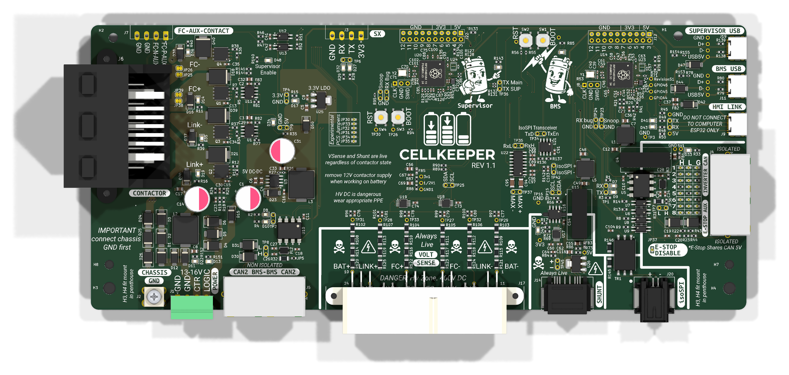
KiCad PCB design for the CellKeeper Battery Management System, a replacement BMS controller for battery packs using the isoSPI protocol. The main board fits the Tesla battery's penthouse: the pack's original harness, HV sense, shunt and BMB connectors plug into it, and it mounts on the original brackets.
Each ordered revision has a release with its Gerbers, JLCPCB BOM and CPL, schematic PDF, board PDF (3D views and 1:1 prints) and the enclosure print files. Rev 1.1 was ordered on 2026-10-28; work towards rev 1.2 is on the rev1.2 branch.
Three boards, each its own KiCad project. They share no copper: the hat and the precharge board connect to the rest of the system by wires and lugs.
| Path | Description |
|---|---|
CellKeeper/ | Main controller board (CellKeeper.kicad_pro). Each ordered revision's Gerbers, BOM, CPL, schematic and board PDFs are on the releases page |
isoSPI-Hat/ | isoSPI hat for a Raspberry Pi Pico: SP3485 / AM26LV32 / HM2113 transformer to the BMB connector |
Precharge/ | Precharge board: six PTCs (three parallel strings of two) between M8 lugs, plus the HV system wiring diagram |
lib/ | Shared CellKeeper_Local symbol and footprint libraries and CellKeeper.3dshapes 3D models |
enclosure/ | 3D-printable case for the main board (build123d) |
graphics/ | Silkscreen artwork and README images |
python_scripts/ | README renders (render_readme_images.py), release files (export_release_files.py), 3D model generators |
docs/ | How to release a revision (releasing.md), README notes |
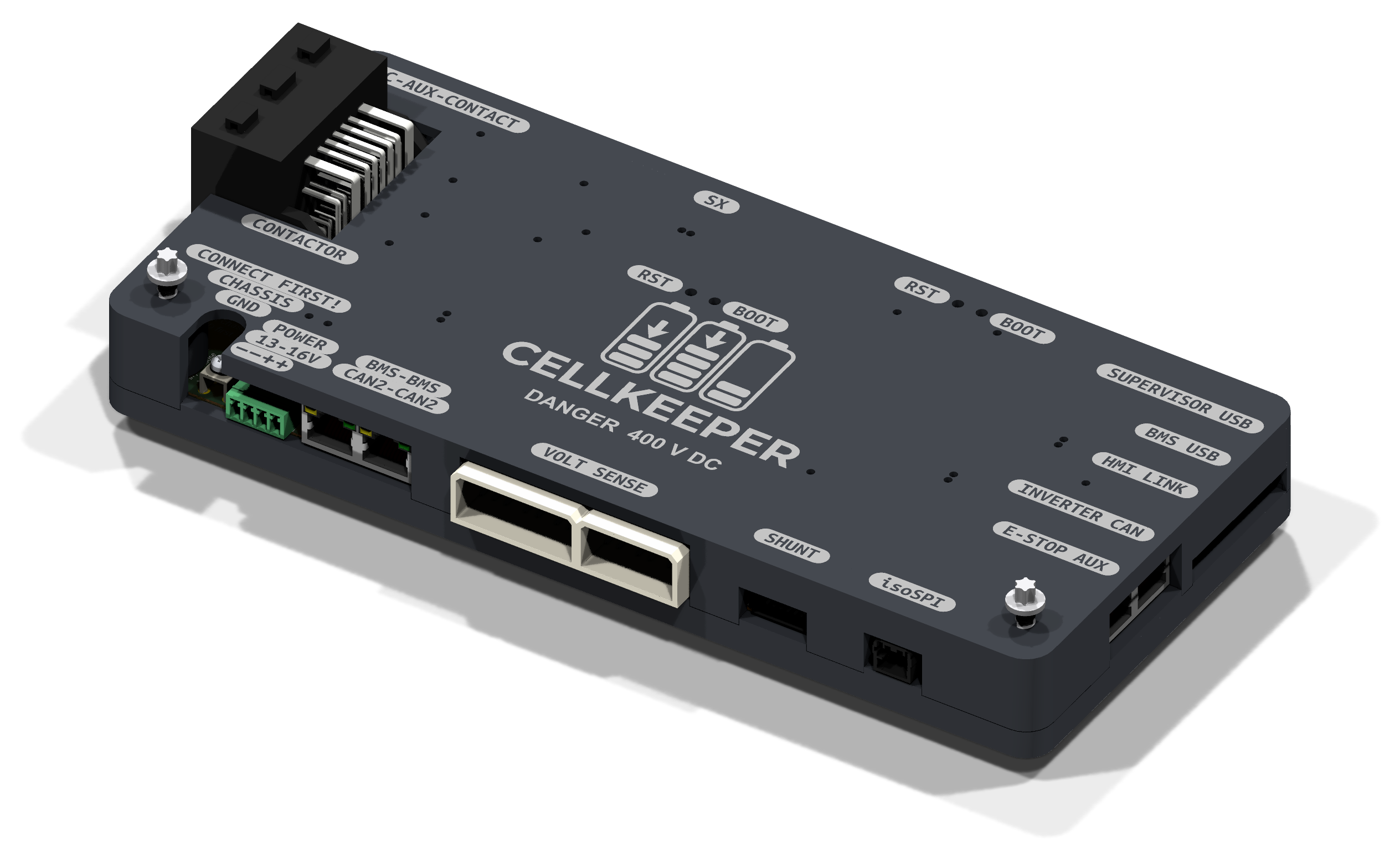
A two-part printed case (base tray and lid) for the main board, generated by
enclosure/cellkeeper_case.py. It mounts in the penthouse on the original HVC brackets. The lid
carries the logo and connector labels, which can be printed as a contrasting-colour inlay, with
open tunnels over the LEDs. Ready-to-print STEP and STL files are attached to each
release; running the script writes
them to enclosure/output/print/.
The board shows the case in KiCad's 3D viewer through the ENC1 footprint.
⚠️ This board interfaces with 400 V battery packs that can deliver lethal current. Only qualified personnel should work on high-voltage systems. This is a v1.1 development design — untested, no warranty, use at your own risk.
GPL-3.0 — see LICENSE.
| Qty | Value | Footprint | References |
|---|---|---|---|
| 6 | B59451C1130B070 | CellKeeper_Local:BMS_Library__RV_Disc_D15.5mm_W7.5mm_P5.0mm | TH1, TH2, TH3, TH4, TH5, TH6 |
| 2 | MountingHole_Pad | CellKeeper_Local:MountingHole__MountingHole_8.4mm_M8_Pad_Via | H1, H2 |


rjwalters/kicad-tools
Standalone Python tools for parsing and manipulating KiCad schematic and PCB files


ras-marques/ImmersiveGloves
I want to share how I am making vr gloves using 2 Tundra Trackers, 2 interface boards and 12 inertial sensors.


It measures 44 × 72.1 mm and has 4 copper layers, 1.6 mm thick.
8 parts, built around the B59451C1130B070. The full list of its parts is on this page, with links to each part's symbol and footprint where PCBKit's library has them.
From the cellkeeper-bms/cellkeeper-hardware repository on GitHub, at the commit this page was made from: the board is Precharge/Precharge.kicad_pcb and its schematic CellKeeper/CellKeeper.kicad_sch. PCBKit opens the board in the browser, with nothing to install.
Its repository publishes it under the GPL-3.0 licence: you may reuse it on that licence's terms (keep the author's notice, and for a copyleft licence share your changes alike).