2 layers40 × 34 mm
 ccadic/SHARPIW018
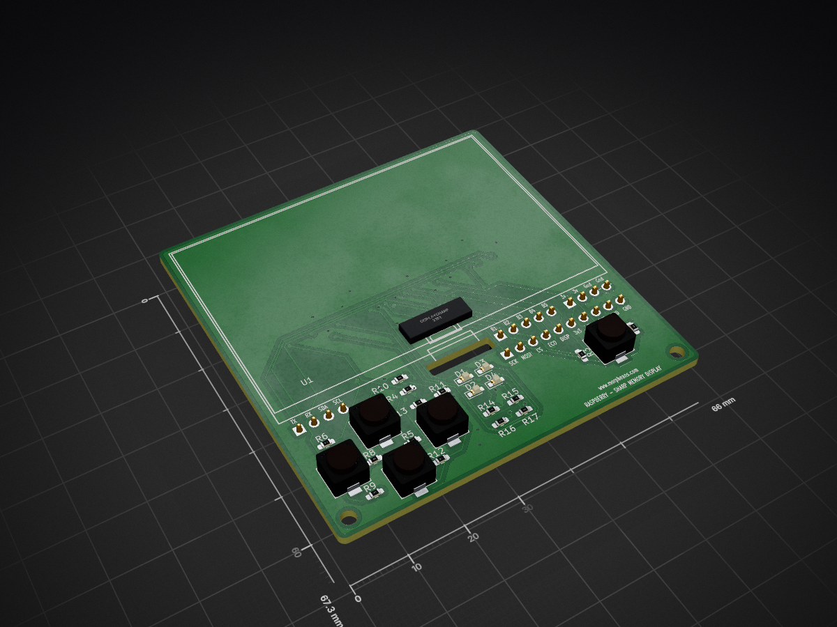
The SHARPIW0 carrier board has been designed to hold both a Raspberry(R) PI ZERO 2W or W + 2.7" (400x240) Sharp Memory Display.
MemoryBrakout is an open-source printed circuit board by ccadic, from the ccadic/SHARPIW0 repository on GitHub. It is a 2-layer board of 66 × 67.3 mm with 37 parts on 31 nets, routed with 408 tracks and 54 vias.
Its parts include 17 resistors, 5 connectors, 5 switches, 4 diodes and 3 capacitors. It belongs with the computers and single-board computers and lEDs and displays boards of this library.

The SHARPIW0 carrier board has been designed to hold both a Raspberry(R) PI ZERO 2W or W + 2.7" (400x240) Sharp Memory Display. This display is capable of a fast refresh which allows the use of linux shells or display game images.
The board also has 4 independently controlable LEDs you can switch on/off with classic GPIO commands (C++ or Python)
The board also has 5 buttons you may also control via GPIO voltage detection (UP/Down voltage detection). You can use this board for gaming.
You can get a fully made board here: https://www.tindie.com/products/electronictrik/sharpiw0-a-rpi-zero-27-sharp-memory-display/ It is also a good way to support opensource devices creators
If you need PCB only: https://www.tindie.com/products/electronictrik/sharpiw0-rpi0w-27-sharp-display-pcb-only/
Extra GPIO available
We added several extra GPIO, should you want to add an external UART extra board or a I2C board. For the maker, we also added access to the display pins with the right bottom line of 2.54 mm header pinout (SCK to GND). If you want, you can drive the LCD without the Raspberry PI ZERO , and replace it with a classic microcontroller. In the same idea, you have B1 to B5 buttons signals available on pins.
Installation If the board and display come separate, please connect the display's ribbon to the white connector, ribbon contacts facing the board surface. Plug the Raspberry PI ZERO like show on the diagram below.
Software setup The Buttons and LEDs are controleable using classic python scripts. For the display, you have to install 2 libraries/code and compile them
1° ONE BITE DISPLAY LIB: https://github.com/bitbank2/OneBitDisplay Install with git clone https://github.com/bitbank2/OneBitDisplay Go to /linux/Sharp_LCD directory and type make.
2° ARMBIANIO LIB: https://github.com/bitbank2/ArmbianIO Install the lib with git clone https://github.com/bitbank2/ArmbianIO and make
Go back to Go to /linux/Sharp_LCD directory and run the compiled executable ./sharp_lcd
Have fun ! Dr CADIC Philippe
Special credits to : Larry Bank for hi precious help and support in this project. @fast_code_r_us
Link to new LCD if an accident occurs Link to SHARP Display: https://fr.aliexpress.com/item/4000674316500.html
| Qty | Value | Footprint | References |
|---|---|---|---|
| 7 | 10k | Resistor_SMD:R_0603_1608Metric_Pad0.98x0.95mm_HandSolder | R2, R4, R6, R7, R8, R10, R11 |
| 5 | 1k | Resistor_SMD:R_0603_1608Metric_Pad0.98x0.95mm_HandSolder | R3, R5, R9, R12, R13 |
| 4 | 330R | Resistor_SMD:R_0603_1608Metric_Pad0.98x0.95mm_HandSolder | R14, R15, R16, R17 |
| 4 | Yellow | LED_SMD:LED_0603_1608Metric_Castellated | D1, D2, D3, D4 |
| 2 | 100nF | Capacitor_SMD:C_0603_1608Metric_Pad1.08x0.95mm_HandSolder | C1, C2 |
| 2 | MountingHole | MountingHole:MountingHole_2.5mm | H1, H2 |
| 1 | 0R | Resistor_SMD:R_0603_1608Metric_Pad0.98x0.95mm_HandSolder | R1 |
| 1 | 1uF | Capacitor_SMD:C_0603_1608Metric_Pad1.08x0.95mm_HandSolder | C3 |
| 1 | 3Vsource | Connector_PinHeader_2.54mm:PinHeader_1x04_P2.54mm_Vertical | J5 |
| 1 | But1 | 18650:SW_TP1003 | SW2 |
| 1 | But2 | 18650:SW_TP1003 | SW1 |
| 1 | But3 | 18650:SW_TP1003 | SW3 |
| 1 | But4 | 18650:SW_TP1003 | SW4 |
| 1 | But5 | 18650:SW_TP1003 | SW5 |
| 1 | Buttons | Connector_PinHeader_2.54mm:PinHeader_1x05_P2.54mm_Vertical | J2 |
| 1 | DisplaySharp | MemoryBrakout:SHARP27LCD | U1 |
| 1 | RPI_Connector-ML_RPi_GPIO | MemoryBrakout:Raspberry_Pi_ZeroREVERSE_SMD | J1 |
| 1 | externalcnx | Connector_PinHeader_2.54mm:PinHeader_1x10_P2.54mm_Vertical | J3 |
| 1 | uart | Connector_PinHeader_2.54mm:PinHeader_1x04_P2.54mm_Vertical | J4 |
It measures 66 × 67.3 mm and has 2 copper layers, 1.6 mm thick.
37 parts. The full list of its parts is on this page, with links to each part's symbol and footprint where PCBKit's library has them.
From the ccadic/SHARPIW0 repository on GitHub, at the commit this page was made from: the board is MemoryBrakout.kicad_pcb. PCBKit opens the board in the browser, with nothing to install.
Its repository states no licence, so its author keeps all rights: ask ccadic before reusing the design.

hoglet67/RGBtoHDMI
Bare-metal Raspberry Pi project that provides pixel-perfect sampling of Retro Computer RGB/YUV video and conversion to HDMI

hackclub/OnBoard
💡 Join 1,000 teenagers and make your first PCB with a $100 grant!

FreeYourStream/freedeck-hardware
all the stuff you need to build your own FreeDeck

stuartpittaway/diyBMS
Do it yourself battery management system for Lithium ion battery packs/cells

Pwnsat/FlatSat
Flatsat v1.0 is a hardware based platform for aerospace cybersecurity research


vsfteam/vsf
Versaloon Software Framework -- a tiny preemptive-capable event-driven incremental software framework for embedded systems