4 layers66 × 115.3 mm
MemoryBrakout
ccadic/sharpikeebo
Miniature RPI Zero 2W shield with Sharp memory Display and USB Beyboard
194 parts143

 ccadic/sharpikeebo143
Miniature RPI Zero 2W shield with Sharp memory Display and USB Beyboard
RAK3172h breadboard is an open-source printed circuit board by ccadic, from the ccadic/sharpikeebo repository on GitHub. It is a 4-layer board of 25.5 × 46.5 mm with 48 parts on 46 nets, routed with 630 tracks and 77 vias.
It is built around the CH340E, ME6211C33M5G-N and RAK3172-SIP. Its parts include 22 resistors, 7 capacitors, 5 diodes, 5 connectors and 5 switches.


**SHARPIKEEBO – Version 2025 (Public Release)
**

**sharpikeebo – V2025 Miniature Raspberry Pi Zero 2W shield with Sharp Memory Display and USB Keyboard ** This repository now documents the public 2025 version of the SHARPIKEEBO, distributed after the successful crowdfunding campaign on Crowd Supply: https://www.crowdsupply.com/morpheans/sharpikeebo
All hardware described here corresponds to the final production version delivered to backers and the public.
Overview
Hello all,
This is the SHARPIKEEBO Nano Computer Shield, built around the famous Raspberry Pi Zero 2W, featuring:
The SHARPIKEEBO was initially designed as a portable SSH and system administration tool, allowing administrators to quickly connect to servers and perform maintenance operations. During development, many users also pointed out its potential as a retro or lightweight gaming platform.
**Hardware Description **
The SHARPIKEEBO carrier board is designed to host:
A Raspberry Pi Zero 2W or Zero W
A 2.7" Sharp Memory Display (400 × 240) capable of fast refresh rates, suitable for: Linux shells Text-based interfaces Simple graphical games Additional features include:
Controllable LEDs (GPIO, usable from C++ or Python)
Easily accessible UART and I²C GPIOs for external modules: GPS 4G / 5G modem Other 3.3 V or 5 V peripherals
Power is supplied via USB-C, and the board can also behave as a USB keyboard device when plugged into a desktop, laptop, or rack server.
**IMPORTANT CHANGES & CLARIFICATION (READ CAREFULLY) ** This section is critical for proper operation of the 2025 public hardware.
**Raspberry Pi Zero mounting orientation (VERY IMPORTANT)
**

The Raspberry Pi Zero must be mounted with its connector facing DOWN
This means the components of the Raspberry Pi remain visible
DO NOT use a 20×2 pin header mounted on the TOP side
If the Raspberry Pi is connected using a top-mounted 20×2 pin header, the board will NOT work
This is not optional and is required by the electrical design of the SHARPIKEEBO.
Battery polarity warning
**** 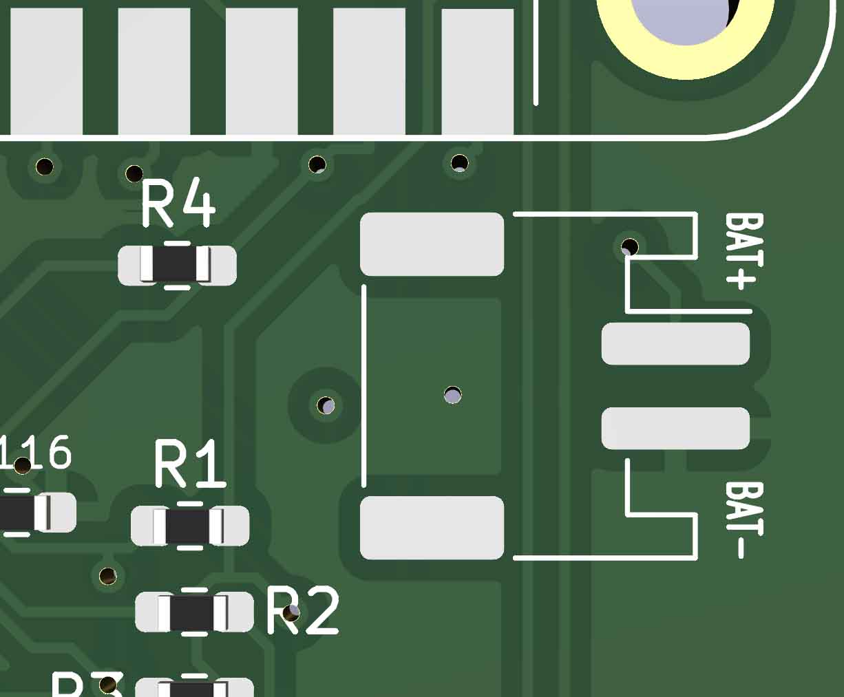
Some batteries on the market do NOT follow standard polarity orientation
Incorrect polarity can permanently damage the board
Always verify battery polarity against the schematics before connecting Never assume wire colors are correct
**RAK Wireless module interface ** The RAK Wireless module is connected in UART mode
It is NOT wired in SPI mode
Any software configuration must therefore use UART, not SPI. Factory testing guarantee
Every single SHARPIKEEBO unit shipped has been individually tested
All boards were:
If you encounter an issue, it is almost always related to:
This repository now reflects the final, stable, production hardware shipped after the Crowd Supply campaign. Future updates will focus on software examples, configurations, and community contributions, not hardware changes.
| Qty | Value | Footprint | References |
|---|---|---|---|
| 4 | 100nF | Capacitor_SMD:C_0603_1608Metric | C101, C102, C104, C105 |
| 4 | 10k | Resistor_SMD:R_0603_1608Metric_Pad0.98x0.95mm_HandSolder | R102, R103, R106, R107 |
| 4 | 1k | Resistor_SMD:R_0603_1608Metric_Pad0.98x0.95mm_HandSolder | R104, R105, R108, R109 |
| 4 | 330R | Resistor_SMD:R_0603_1608Metric | R114, R115, R116, R122 |
| 2 | 0R | Resistor_SMD:R_0603_1608Metric_Pad0.98x0.95mm_HandSolder | R118, R119 |
| 2 | 1uF | Capacitor_SMD:C_0603_1608Metric | C106, C107 |
| 2 | 22R | Resistor_SMD:R_0603_1608Metric | R110, R111 |
| 2 | 4.7k | Resistor_SMD:R_0603_1608Metric | R120, R121 |
| 2 | 5.1K | Resistor_SMD:R_0603_1608Metric | R112, R113 |
| 1 | 1.2k | Resistor_SMD:R_0603_1608Metric_Pad0.98x0.95mm_HandSolder | R117 |
| 1 | 10k | Resistor_SMD:R_0603_1608Metric | R101 |
| 1 | 10uF | Capacitor_SMD:C_0603_1608Metric | C103 |
| 1 | BOOT | 27sharp:SKRPABE010 | SW105 |
| 1 | BUT1 | 18650:SW_TP1003 | SW101 |
| 1 | BUT2 | 18650:SW_TP1003 | SW102 |
| 1 | BUT3 | 18650:SW_TP1003 | SW103 |
| 1 | BUT4 | 18650:SW_TP1003 | SW104 |
| 1 | CH340E | Package_SO:MSOP-10_3x3mm_P0.5mm | U102 |
| 1 | FDTI | Connector_PinHeader_2.54mm:PinHeader_1x06_P2.54mm_Vertical | J106 |
| 1 | GPIOs | Connector_PinSocket_2.54mm:PinSocket_1x12_P2.54mm_Vertical | J101 |
| 1 | GreenL | LED_SMD:LED_0603_1608Metric | D102 |
| 1 | ME6211C33M5G-N | Package_TO_SOT_SMD:SOT-23-5 | U104 |
| 1 | MiniCoax | 18650:Molex_Microcoaxial_RF | J102 |
| 1 | OLED12832 | 18650:OLED-0.91-128x32 | U103 |
| 1 | Program | Connector_PinHeader_2.54mm:PinHeader_1x05_P2.54mm_Vertical | J105 |
| 1 | RAK3172 | 27sharp:RAK3172 | U101 |
| 1 | RX-GREEN | LED_SMD:LED_0603_1608Metric | D105 |
| 1 | RX-RED | LED_SMD:LED_0603_1608Metric | D103 |
| 1 | TX-YEL | LED_SMD:LED_0603_1608Metric | D101 |
| 1 | USB_C_Receptacle | 27sharp:GT-USB-7010 | J104 |
| 1 | Violet | LED_SMD:LED_0603_1608Metric | D104 |
It measures 25.5 × 46.5 mm and has 4 copper layers, 1.6 mm thick.
48 parts, built around the CH340E, ME6211C33M5G-N and RAK3172-SIP. The full list of its parts is on this page, with links to each part's symbol and footprint where PCBKit's library has them.
From the ccadic/sharpikeebo repository on GitHub, at the commit this page was made from: the board is update2026/kicad_files/rak3172/RAK3172h-breadboard/RAK3172h-breadboard.kicad_pcb and its schematic update2026/kicad_files/MemoryBrakout.kicad_sch. PCBKit opens the board in the browser, with nothing to install.
Its repository states no licence, so its author keeps all rights: ask ccadic before reusing the design.
ccadic/sharpikeebo
Miniature RPI Zero 2W shield with Sharp memory Display and USB Beyboard

ccadic/sharpikeebo
Miniature RPI Zero 2W shield with Sharp memory Display and USB Beyboard

ccadic/sharpikeebo
Miniature RPI Zero 2W shield with Sharp memory Display and USB Beyboard

ccadic/sharpikeebo
Miniature RPI Zero 2W shield with Sharp memory Display and USB Beyboard

teapotlaboratories/feather-rak3172
Teapotlabs Feather RAK3172: Low-cost Low-power LoRaWAN Development Board

diegobouvier/Wisflow-lora_valve_controller
Kicad proyecto for a LoRa remote valve controler actuator

ISS-Lab-Unibo/Agro_LoRaInductiveFruitGauge
An open-source, low-cost and low-power LoRaWAN sensor node for continuous, non-destructive monitoring of fruit growth directly on the tree, together with the high-resolution inductive fruit gauges (pliers) it reads.

Stratolink-hq/Stratolink
An open source, upper-atmospheric, pico balloon platform.

emertcakir/OpenAirScope
Open-source air quality and environmental monitoring node with STM32H743 + ESP32-C3, LoRaWAN, RS485, USB-C, Li-ion charging, and multi-sensor support.

teapotlaboratories/bwlr3d
Teapot BWLR3D: Asset Tracker and Environmental Sensor with Solar Energy Harvesting

