

2 layers150 × 150 mm
BirtdayCard
Casperdroid5/BirthdayCard
Personal message ESP32 C3 wroom02 module based birthday card PCB for my brother
57 parts

 Casperdroid5/Kinderdorp-PCB
An interactive educational PCB designed for children to learn electronics through hands-on experimentation with LEDs, sensors, and programming.
Kinderdorp PCB is an open-source printed circuit board by Casperdroid5, from the Casperdroid5/Kinderdorp-PCB repository on GitHub. It is a 2-layer board of 99.1 × 99.1 mm with 44 parts on 42 nets, routed with 214 tracks and 40 vias.
It is built around the WS2812B and DTSM-61R-V-T/R. Its parts include 11 diodes, 9 resistors, 4 capacitors, 2 ICs and 1 transistor. It belongs with the ESP32 and RISC-V boards of this library.
An interactive educational PCB designed for children to learn electronics through hands-on experimentation with LEDs, sensors, and programming.
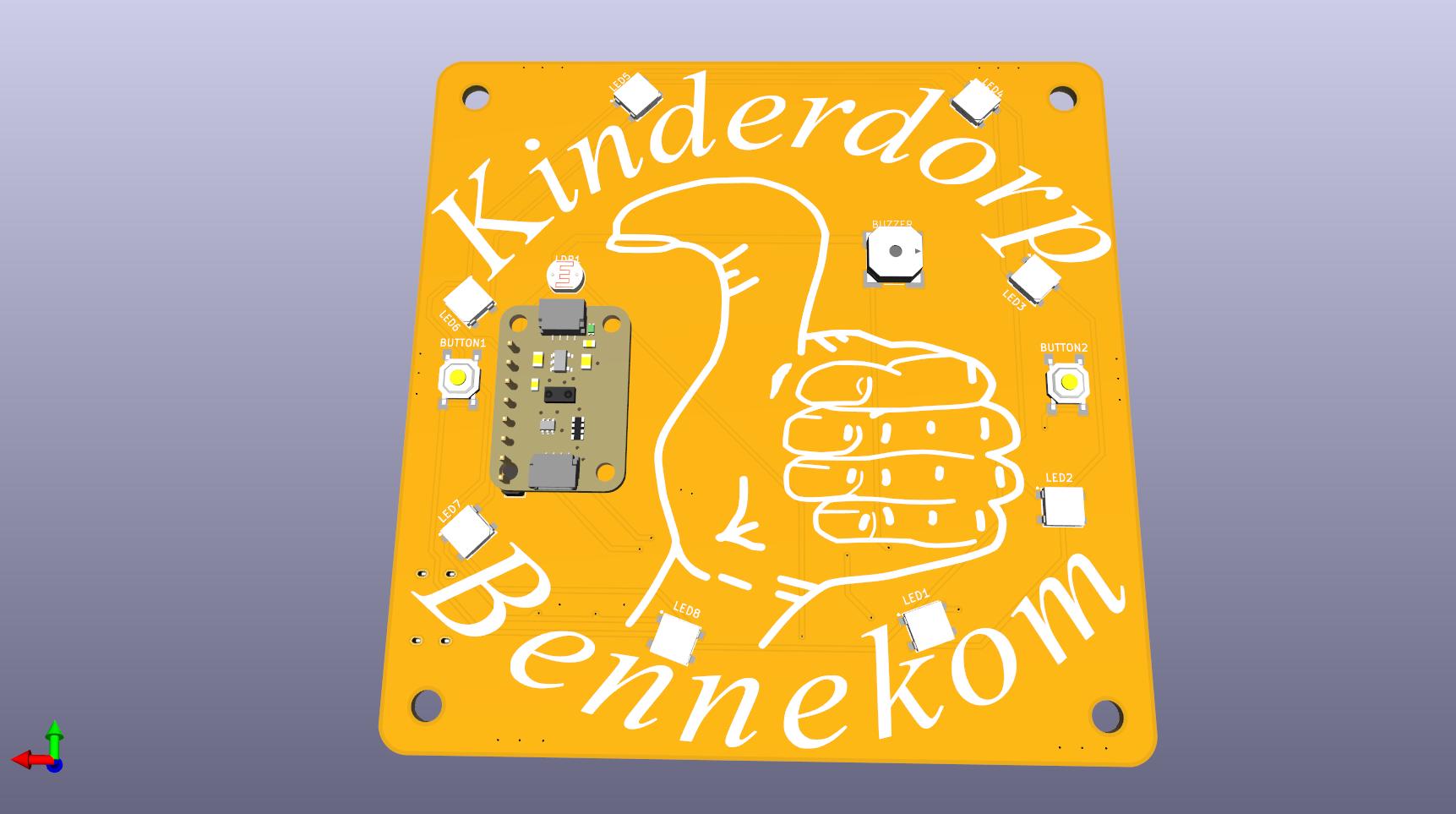
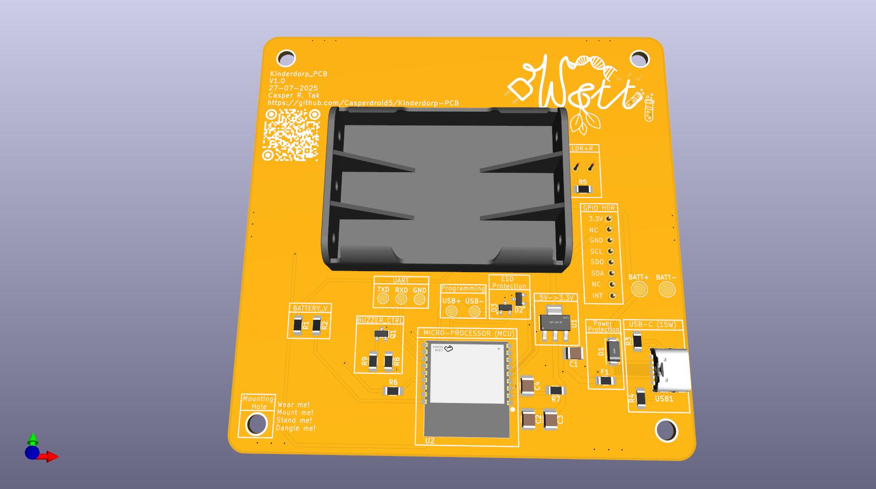
The Kinderdorp PCB is an ESP32-C3 based learning platform featuring addressable RGB LEDs, user input buttons, sensors, and multiple power options. The board includes fun visual elements and is designed to be both educational and engaging for young learners.
| Component | Specification |
|---|---|
| Microcontroller | ESP32-C3-WROOM-02-N4 (4MB) |
| Operating Voltage | 3.3V |
| Power Input | 5V via USB-C or 3-6V battery |
| LEDs | 8x WS2812B RGB (5050 package) |
| Buttons | 2x DTSM-61R tactile switches |
| Buzzer | KSSGK4B16-20 |
| Light Sensor | LDR07 photoresistor |
| PCB Dimensions | ~100mm x 100mm |
GPIO0  - Programming/Boot button
GPIO1  - UART TX (programming)
GPIO3  - UART RX (programming)
GPIO4  - User Button 1
GPIO5  - RGB LED Data Out
GPIO6  - SDA (I2C)
GPIO7  - SCL (I2C)
GPIO8  - User Button 2
GPIO9  - Buzzer Control
GPIO10 - Light Sensor (ADC)
GPIO18 - Battery Voltage Monitor
GPIO19 - RGB LED Data InThe 8 WS2812B LEDs are connected in series:
LED1 → LED2 → LED3 → LED4 → LED5 → LED6 → LED7 → LED8
#include <FastLED.h>

#define LED_PIN 19
#define NUM_LEDS 8
#define BUTTON1_PIN 4
#define BUTTON2_PIN 8
#define BUZZER_PIN 9
#define LDR_PIN 10

CRGB leds[NUM_LEDS];

void setup() {
  FastLED.addLeds<WS2812B, LED_PIN, GRB>(leds, NUM_LEDS);
  pinMode(BUTTON1_PIN, INPUT_PULLUP);
  pinMode(BUTTON2_PIN, INPUT_PULLUP);
  pinMode(BUZZER_PIN, OUTPUT);
}

void loop() {
  // Rainbow effect
  for(int i = 0; i < NUM_LEDS; i++) {
    leds[i] = CHSV(i * 32, 255, 255);
  }
  FastLED.show();
  delay(100);
}float getBatteryVoltage() {
int rawValue = analogRead(18);
// Voltage divider: 6V→3V, 4.5V→2.25V, 3V→1.5V, 2V→1V
return (rawValue / 4095.0) * 3.3 * 2.0;
}The PCB includes playful design elements:
This project is released under the MIT License. Feel free to use, modify, and distribute for educational purposes.
Casper R. Tak
Kinderdorp PCB - Making electronics fun and accessible for young (and older) minds! 🌟
| Qty | Value | Footprint | References |
|---|---|---|---|
| 8 | WS2812B | easyeda2kicad:LED-SMD_4P-L5.0-W5.0-BL_TC5050RGB | LED1, LED2, LED3, LED4, LED5, LED6, LED7, LED8 |
| 5 | TestPoint_Probe | TestPoint:TestPoint_Pad_D2.0mm | GND, RX, TX, USB-, USB+ |
| 4 | 10k | Resistor_SMD:R_1206_3216Metric_Pad1.30x1.75mm_HandSolder | R1, R2, R7, R8 |
| 2 | 47uF 10V | Capacitor_SMD:C_1210_3225Metric_Pad1.33x2.70mm_HandSolder | C1, C3 |
| 2 | 5k1 | Resistor_SMD:R_1206_3216Metric_Pad1.30x1.75mm_HandSolder | R3, R4 |
| 2 | DTSM-61R-V-T/R | easyeda2kicad:KEY-SMD_4P-L6.2-W6.2-P4.50-LS9.0 | BUTTON1, BUTTON2 |
| 2 | LOGO | LOGO | G***, G*** |
| 2 | SM712_SOT23 | Package_TO_SOT_SMD:SOT-23 | D2, D3 |
| 1 | 100 | Resistor_SMD:R_1206_3216Metric_Pad1.30x1.75mm_HandSolder | R9 |
| 1 | 100nF 50V | Capacitor_SMD:C_1210_3225Metric_Pad1.33x2.70mm_HandSolder | C2 |
| 1 | 10uF 25V | Capacitor_SMD:C_1210_3225Metric_Pad1.33x2.70mm_HandSolder | C4 |
| 1 | 1N5819_C437199 | easyeda2kicad:SMA_L4.4-W2.6-LS5.0-RD | D1 |
| 1 | 200 | Resistor_SMD:R_1206_3216Metric_Pad1.30x1.75mm_HandSolder | R6 |
| 1 | 2N7002_C306856 | easyeda2kicad:SOT-23-3_L2.9-W1.3-P1.90-LS2.4-BR | Q1 |
| 1 | 5k | Resistor_SMD:R_1206_3216Metric_Pad1.30x1.75mm_HandSolder | R5 |
| 1 | AMS1117-3.3_C347222 | easyeda2kicad:SOT-223-4_L6.5-W3.5-P2.30-LS7.0-BR | U1 |
| 1 | Batteryplaceholder | MountingHole:MountingHole_2.1mm | BATTPACK1 |
| 1 | Conn_01x08 | Connector_PinHeader_2.54mm:PinHeader_1x08_P2.54mm_Vertical | HDR1 |
| 1 | ESP32-C3-WROOM-02-N4(4MB) | easyeda2kicad:BULETM-SMD_ESPRESSIF_ESP32-C3-WROOM-02-N4-4MB | U2 |
| 1 | KSSGK4B16-20 | CustomPartsCRT:KSSGK4B16-20 | LS1 |
| 1 | LDR07 | OptoDevice:R_LDR_5.1x4.3mm_P3.4mm_Vertical | LDR1 |
| 1 | Resetable fuse 0.75A | Fuse:Fuse_1206_3216Metric_Pad1.42x1.75mm_HandSolder | F1 |
| 1 | TYPE-C 6P(073) | easyeda2kicad:TYPE-C-SMD_TYPE-C-6P_5 | USB1 |
| 1 | TestPoint_Alt | TestPoint:TestPoint_Pad_D3.0mm | BATT- |
| 1 | ~ | TestPoint:TestPoint_Pad_D3.0mm | BATT+ |
It measures 99.1 × 99.1 mm and has 2 copper layers, 1.6 mm thick.
44 parts, built around the WS2812B and DTSM-61R-V-T/R. The full list of its parts is on this page, with links to each part's symbol and footprint where PCBKit's library has them.
From the Casperdroid5/Kinderdorp-PCB repository on GitHub, at the commit this page was made from: the board is Kinderdorp_PCB.kicad_pcb and its schematic Kinderdorp_PCB.kicad_sch. PCBKit opens the board in the browser, with nothing to install.
Its repository states no licence, so its author keeps all rights: ask Casperdroid5 before reusing the design.
Casperdroid5/BirthdayCard
Personal message ESP32 C3 wroom02 module based birthday card PCB for my brother

Casperdroid5/Christmas-PCBs
This project provides hardware and firmware for an ESP32-C3 based Christmas-themed PCB that controls an array of addressable LEDs and plays Christmas songs via a buzzer.

fossasia/pslab-hardware
PSLab Hardware Design and Schematics https://pslab.io

FrameworkComputer/ExpansionCards
Reference designs and documentation to create Expansion Cards for the Framework Laptop


PrintersForAnts/Micron
If you want to purchase full kits there are 3 available (Kits are slowly updating to R1 hardware just make sure to double check the included hardware in your kit and if you have any questions reach out in the discord)
