2 layers168 × 109.2 mm
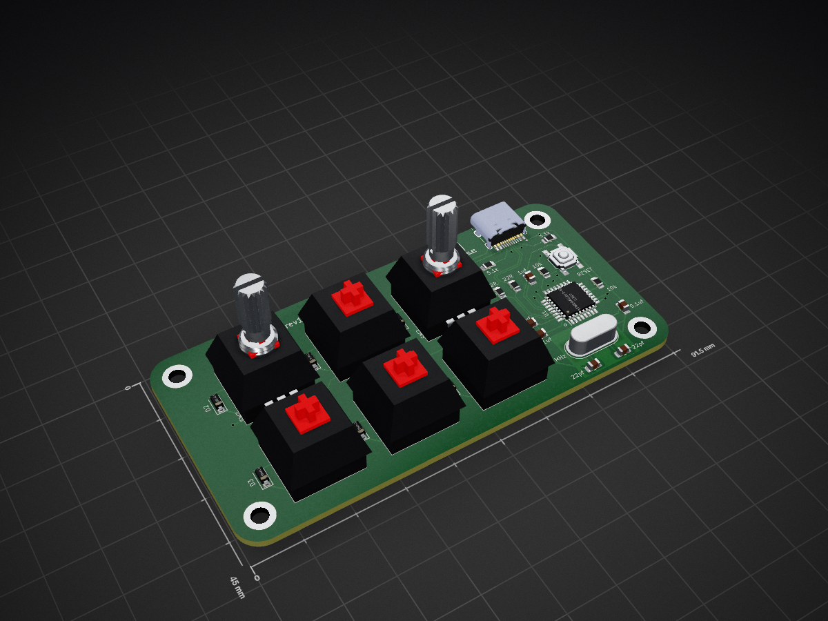
 CASE-Association/CASE_keypad4
2x3 Keypad kit
CASE keypad is an open-source printed circuit board by CASE-Association, from the CASE-Association/CASE_keypad repository on GitHub, published under the MIT licence. It is a 2-layer board of 91.5 × 45 mm with 35 parts on 41 nets, routed with 276 tracks and 20 vias.
It is built around the ATMEGA32U2-AU and TYPE-C-31-M-12. Its parts include 8 switches, 6 diodes, 1 IC and 1 connector. It belongs with the keyboards and input boards and the AVR (ATmega, ATtiny) boards of this library.


2x3 Keypad kit
This kit requires SMD soldering of 0805 components and a QFP microcontroller. See this for quick guide in hand-soldering SMD components Recommended soldering order:
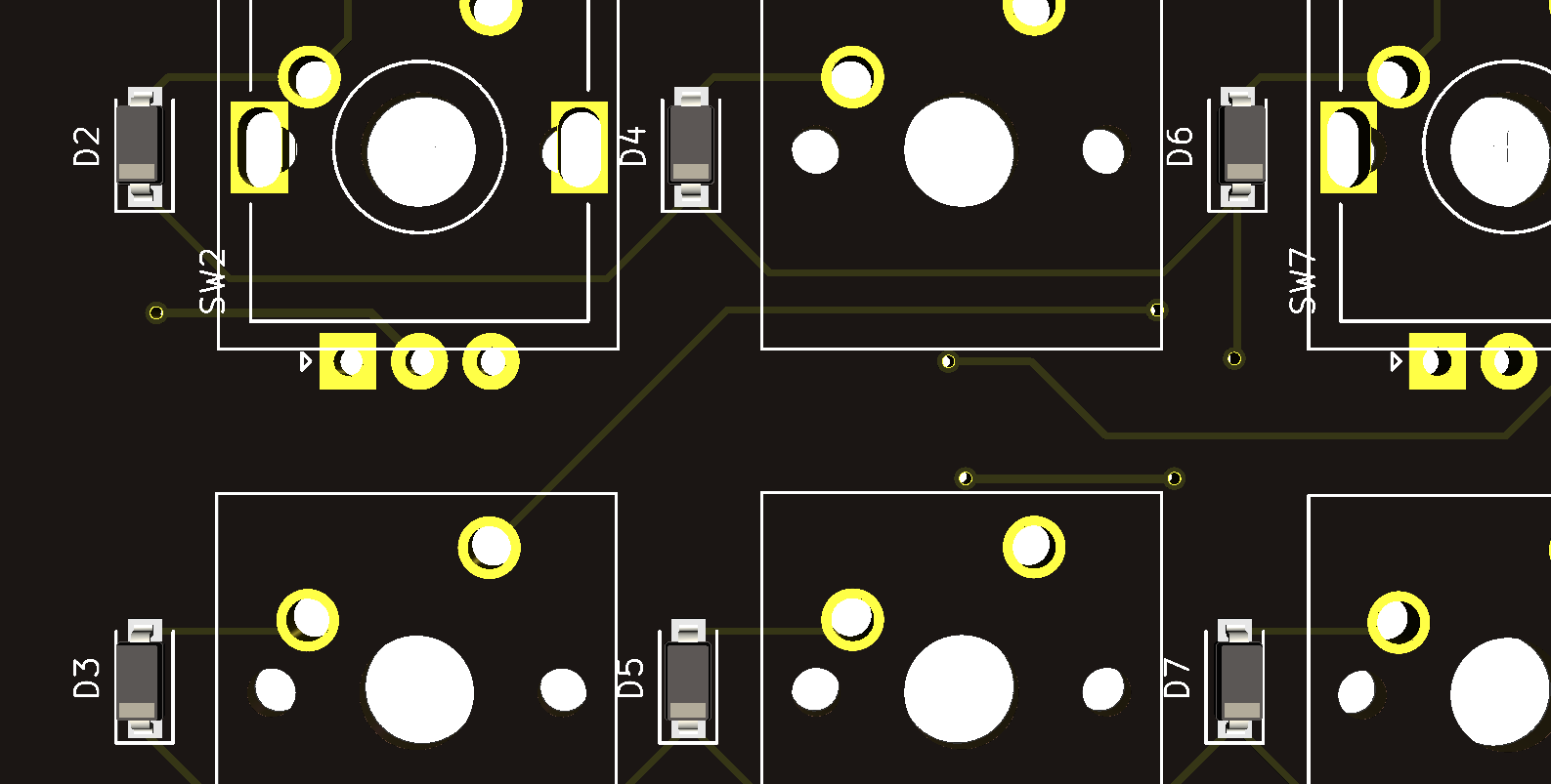
Diodes have to be soldered in correct orientation. White line facing downwards.
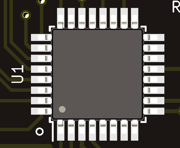
Dot on microcontroller should align with white dot on PCB.
Rest of the components can be soldered in arbitrary orientation.
The keypad can be tested and flashed after soldering the crystal.
Keypad should be flashed and ready to test. Use a jumper wire or tweezers to short the switch pins. The keypad should print numbers 1 to 6.
If flashing does not work, try using v0.0.21 of QMK toolbox
You can now solder the switches/encoder. Encoder is optional and can only be soldered in either top corner (ONLY ONE).
The keybinds can now be configured.
This is a common problem. Plug in the keyboard and open the device manager. The keyboard should show up as ATmega32U2, if it instead shows up as unknown device, something is wrong. Follow these steps:
| Qty | Value | Footprint | References |
|---|---|---|---|
| 6 | D_Small | Diode_SMD:D_SOD-123 | D2, D3, D4, D5, D6, D7 |
| 6 | SW_KEYSW | Button_Switch_Keyboard:SW_Cherry_MX_1.00u_PCB | SW3, SW4, SW5, SW6, SW8, SW9 |
| 2 | 0.1uF | Capacitor_SMD:C_0805_2012Metric_Pad1.18x1.45mm_HandSolder | 0.1uf, 0.1uf |
| 2 | 10k | Resistor_SMD:R_0805_2012Metric_Pad1.20x1.40mm_HandSolder | 10k, 10k |
| 2 | 22 pF | Capacitor_SMD:C_0805_2012Metric_Pad1.18x1.45mm_HandSolder | 22pf, 22pf |
| 2 | 22R | Resistor_SMD:R_0805_2012Metric_Pad1.20x1.40mm_HandSolder | 22R, 22R |
| 2 | 5.1k | Resistor_SMD:R_0805_2012Metric_Pad1.20x1.40mm_HandSolder | 5.1k, 5.1k |
| 2 | Encoder | Rotary_Encoder:RotaryEncoder_Alps_EC11E-Switch_Vertical_H20mm | SW2, SW7 |
| 1 | 10uF | Capacitor_SMD:C_0805_2012Metric_Pad1.18x1.45mm_HandSolder | 10uf |
| 1 | 16 MHz | Crystal:Crystal_HC49-4H_Vertical | 16 MHz |
| 1 | 1uF | Capacitor_SMD:C_0805_2012Metric_Pad1.18x1.45mm_HandSolder | 1uf |
| 1 | ATmega32U2-AU | Package_QFP:TQFP-32_7x7mm_P0.8mm | U1 |
| 1 | LOGO | logo:case_head_9x5mm | G*** |
| 1 | RESET | Button_Switch_SMD:SW_SPST_SKQG_WithStem | RESET |
| 1 | TYPE-C-31-M-12 | usb_c:HRO_TYPE-C-31-M-12 | J1 |
The 31 most common of 35 parts.


cookpad/cookpad-pad
Cookpad Pad — A six keys macro pad made by Cookpad.


ScatteredDrifter/Endeavour
An 38 key orthogonal Keyboard with 3d printable case

simoninns/TMS6100-Emulator
TMS6100 speech PHROM (PHrase Read Only Memory) hardware emulator for use with the TMS5220 Voice Synthesis Processor in an Acorn BBC Microcomputer
It measures 91.5 × 45 mm and has 2 copper layers, 1.6 mm thick.
35 parts, built around the ATMEGA32U2-AU and TYPE-C-31-M-12. The full list of its parts is on this page, with links to each part's symbol and footprint where PCBKit's library has them.
From the CASE-Association/CASE_keypad repository on GitHub, at the commit this page was made from: the board is Hardware/case_keypad/case_keypad.kicad_pcb and its schematic Hardware/case_keypad/case_keypad.kicad_sch. PCBKit opens the board in the browser, with nothing to install.
Its repository publishes it under the MIT licence: you may reuse it on that licence's terms (keep the author's notice, and for a copyleft licence share your changes alike).