2 layers280 × 186 mm

 Casandro/time-marker
A simple time marker
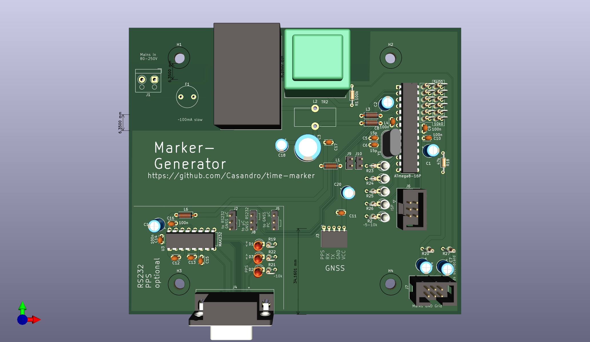
Time marker is an open-source printed circuit board by Casandro, from the Casandro/time-marker repository on GitHub, published under the CC0-1.0 licence. It is a 2-layer board of 132 × 114 mm with 77 parts on 70 nets, routed with 308 tracks and 0 vias.
It is built around the ATMEGA8-16PC, MAX232N and IRM-03-5. Its parts include 24 resistors, 20 capacitors, 10 connectors, 8 diodes and 5 inductors. It belongs with the AVR (ATmega, ATtiny) boards of this library.


This is a small device designed to monitor the frequency of power grids. It consists of a piece of hardware which generates GNSS synced audio markers, and isolates and down-scales it so both can be fed into a sound-card.
From there software will read the markers and generate down-sampled, but propperly timed audio files.
          GNSS (GPS, Galileo, etc)
                   |
Mains grid---Time Marker hardware-----Line-IN of PC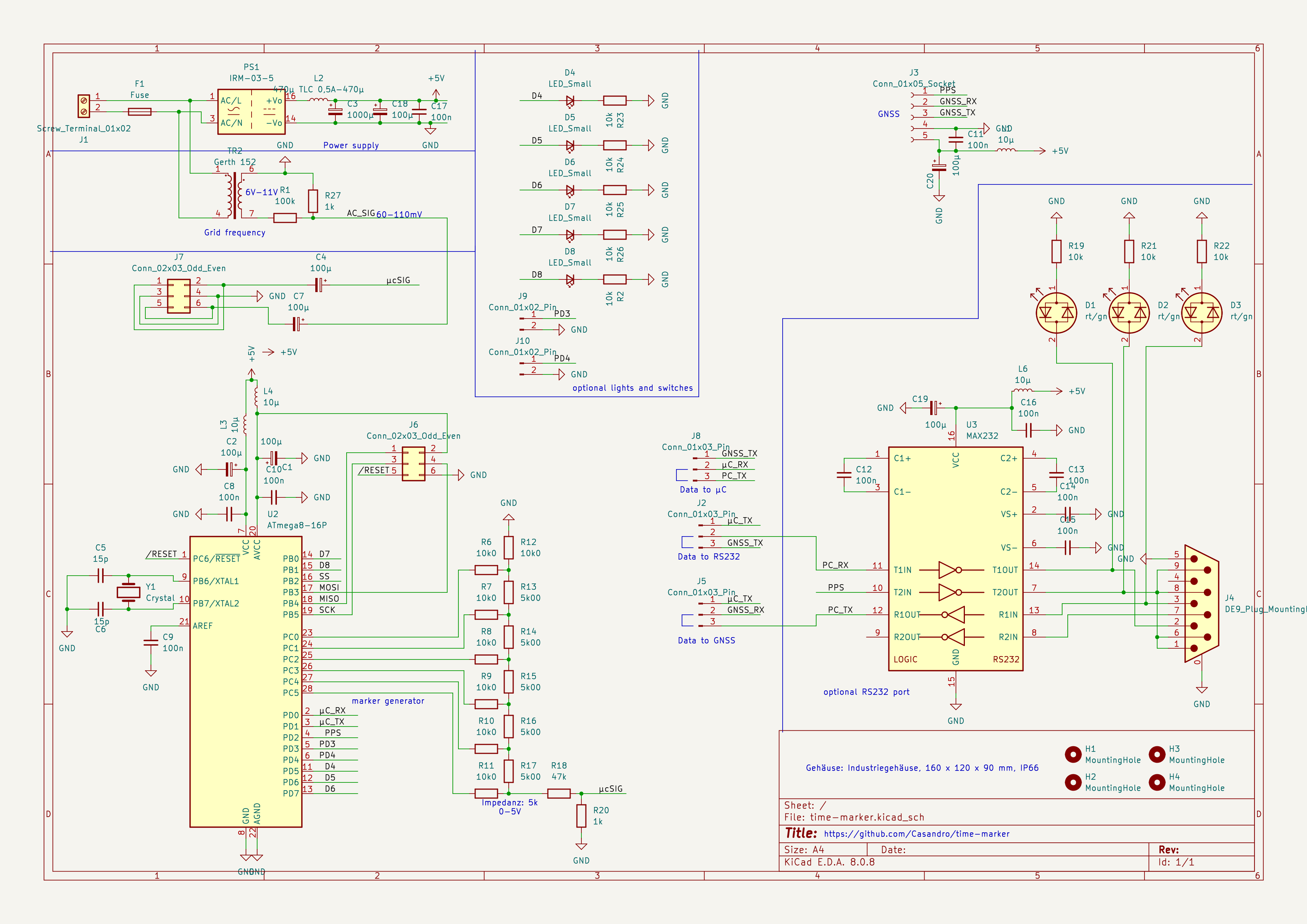
The hardware will get an interrupt from the PPS signal from the GNSS receiver as well as the time via serial. This will start playing a correlation sample, then some data containing the current time. Optionally you can also put that signal onto an RS-232 port, which is useful for getting the PPS signal into your PC.
The idea is that soundcards typically have very decent AD converters, usually having sample rates of at least 48kHz and sample depths of at least 16 Bits. It's hard to do that with easy to get chips. However the clock of those is very much undefined, plus there is an unknown amount of latency between the analog input and the application getting the data.
To circumvent this, the hardware generates markers on one channel, so the other channel is free for whatever signal you want to sample.
The format is not yet defined, however it'll likely use either FSK or DTMF for the data. There will be a sync mark at the beginning of the second, since this is when the timing error is lowest. It will be something with good correlation properties.
A DTMF tone typically is recommended to be at least 50 ms long with a pause of 20 ms between two digits. This means that in a second we could have 14 digits. Leaving some room for the second marker and silence at the end, we could, for exmample, have 10 digits per second. One marker, 8 data digits and one parity or stop digit. The advantage is that DTMF has discrete tones so we can easily have a gap at the end of the signal.
With FSK, we could, for example, have V.21 modulated bits. We'd probably have something like 256 data bits when we subtract run-in periods and the like. We probably need to re-sync it as part of the second mark.
No software is written so far, however it would probably work like this:
Since we will likely not be able to get good data on harmonics, it may be sensible to only look at the 50 Hz peak. For this we can do an IQ demodulation at 50 Hz, downsample this to, for example, 10 or 25 Hz, and only store that IQ data. In principle we can also just store the phase data.
| Qty | Value | Footprint | References |
|---|---|---|---|
| 10 | 100n | Capacitor_THT:C_Disc_D3.0mm_W2.0mm_P2.50mm | C8, C9, C10, C11, C12, C13, C14, C15, C16, C17 |
| 8 | 10k | Resistor_THT:R_Axial_DIN0204_L3.6mm_D1.6mm_P2.54mm_Vertical | R2, R19, R21, R22, R23, R24, R25, R26 |
| 7 | 100µ | Capacitor_THT:CP_Radial_D5.0mm_P2.50mm | C1, C2, C4, C7, C18, C19, C20 |
| 7 | 10k0 | Resistor_THT:R_Axial_DIN0204_L3.6mm_D1.6mm_P2.54mm_Vertical | R6, R7, R8, R9, R10, R11, R12 |
| 5 | 5k00 | Resistor_THT:R_Axial_DIN0204_L3.6mm_D1.6mm_P2.54mm_Vertical | R13, R14, R15, R16, R17 |
| 5 | LED_Small | LED_THT:LED_D3.0mm_Clear | D4, D5, D6, D7, D8 |
| 4 | 10µ | Inductor_THT:L_Axial_L5.3mm_D2.2mm_P7.62mm_Horizontal_Vishay_IM-1 | L1, L3, L4, L6 |
| 4 | MountingHole | MountingHole:MountingHole_4.3mm_M4 | H1, H2, H3, H4 |
| 3 | Conn_01x03_Pin | Connector_PinHeader_2.54mm:PinHeader_1x03_P2.54mm_Vertical | J2, J5, J8 |
| 3 | rt/gn | LED_THT:LED_D3.0mm | D1, D2, D3 |
| 2 | 15p | Capacitor_THT:C_Disc_D3.0mm_W2.0mm_P2.50mm | C5, C6 |
| 2 | 1k | Resistor_THT:R_Axial_DIN0204_L3.6mm_D1.6mm_P2.54mm_Vertical | R20, R27 |
| 2 | Conn_01x02_Pin | Connector_PinHeader_2.54mm:PinHeader_1x02_P2.54mm_Vertical | J9, J10 |
| 2 | Conn_02x03_Odd_Even | Connector_IDC:IDC-Header_2x03_P2.54mm_Vertical | J6, J7 |
| 1 | 1000µ | Capacitor_THT:CP_Radial_D10.0mm_P5.00mm | C3 |
| 1 | 100k | Resistor_THT:R_Axial_DIN0204_L3.6mm_D1.6mm_P7.62mm_Horizontal | R1 |
| 1 | 470µ TLC 0,5A-470µ | Inductor_THT:L_Toroid_Vertical_L16.3mm_W7.1mm_P7.11mm_Pulse_H | L2 |
| 1 | 47k | Resistor_THT:R_Axial_DIN0204_L3.6mm_D1.6mm_P7.62mm_Horizontal | R18 |
| 1 | ATmega8-16P | Package_DIP:DIP-28_W7.62mm | U2 |
| 1 | Conn_01x05_Socket | Connector_PinSocket_2.00mm:PinSocket_1x05_P2.00mm_Horizontal | J3 |
| 1 | Crystal | Crystal:Crystal_HC49-U_Vertical | Y1 |
| 1 | DE9_Plug_MountingHoles | Connector_Dsub:DSUB-9_Female_Horizontal_P2.77x2.84mm_EdgePinOffset4.94mm_Housed_MountingHolesOffset4.94mm | J4 |
| 1 | Fuse | Fuse:Fuse_Littelfuse_372_D8.50mm | F1 |
| 1 | Gerth 152 | Transformer_THT:Transformer_Breve_TEZ-22x24 | TR2 |
| 1 | IRM-03-5 | Converter_ACDC:Converter_ACDC_MeanWell_IRM-03-xx_THT | PS1 |
| 1 | MAX232 | Package_DIP:DIP-16_W7.62mm | U3 |
| 1 | Screw_Terminal_01x02 | TerminalBlock_RND:TerminalBlock_RND_205-00001_1x02_P5.00mm_Horizontal | J1 |
It measures 132 × 114 mm and has 2 copper layers, 1.6 mm thick.
77 parts, built around the ATMEGA8-16PC, MAX232N and IRM-03-5. The full list of its parts is on this page, with links to each part's symbol and footprint where PCBKit's library has them.
From the Casandro/time-marker repository on GitHub, at the commit this page was made from: the board is hardware/time-marker/time-marker.kicad_pcb and its schematic hardware/time-marker/time-marker.kicad_sch. PCBKit opens the board in the browser, with nothing to install.
Its repository publishes it under the CC0-1.0 licence: you may reuse it on that licence's terms (keep the author's notice, and for a copyleft licence share your changes alike).

ondras12345/electronic-load
Digital control for XHDZ-FZ-2g electronic load

phastmike/tmv7displaymod
This repository contains a PCB design for a solution, to the "failing LCD display problem", by OE9MKV. The implementation is based on reverse engineering some parts of the proprietary serial protocol from Kenwood.


qasimgulzar/atmega328-usb-interface-pcb
This project is a simple USB programmer for the ATMEGA328P microcontroller. It allows you to program the microcontroller using a USB connection.


