2 layers125.1 × 87.8 mm
PREN PCB
janvogelTAET/PREN
This repository contains the control software for the PREN Puzzle Robot (Lucerne University of Applied Sciences and Arts).
66 parts

 calphool/JX8P_PSU
Replacement power supply for Roland JX8P
JX8P PSU is an open-source printed circuit board by calphool, from the calphool/JX8P_PSU repository on GitHub, published under the MIT licence. It is a 2-layer board of 123.5 × 112.1 mm with 32 parts on 17 nets, routed with 108 tracks and 1 via.
It is built around the RAC20-05SK, RAC20-07SK and RAC20-15DK, with the EEU-FR1J101B, EEUFR1V471L and BZW04-5V8 among its other parts. Its parts include 8 diodes, 4 capacitors, 4 resistors, 4 connectors and 1 fuse. It belongs with the power boards of this library.


Replacement power supply for Roland JX8P
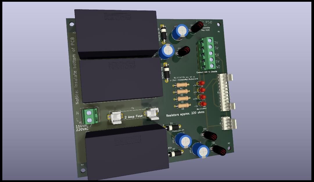
The power supply for the Roland JX8P is nearly 40 years old at this point, and if you own a JX8P you should probably be a little concerned about its typical manner of failing, which is to spike the +5V rail (your logic rail) frying lots of logic chips on your synth. It is also built around heat generating linear regulators, which makes its demise even more likely.
I decided to replace mine preventatively, and this project is the result of that effort. It's basically three Recom power modules with a common ground, and various conditioning components on the output side to make sure we have perfectly smooth rails, despite the fact that these are switching rather than linear supplies. It works fabulously.
The LEDs and resistors near them are optional, but they give you an easy way to identify that all 4 rails are operating properly.
Be aware that this
PCB is managing mains voltages, so don't take on this project if you don't know what you're doing, or if this is a first attempt at building a PCB.
Don't fool with mains voltages unless you know precisely how to protect yourself.
Also be aware that this PCB needs insulation on the bottom of the board. The JX8P uses a shielded metal foil that is grounded. You'll get fireworks if you just plunk this PCB down and connect it. I used a sheet of plexiglass, and attached the board and plexiglass to the wooden base of the synth using 6-32 nylon screws and nuts.
I sourced all the components from Mouser, though you can probably find them anywhere.
The board has some safety features. Since what we care about is the synth, I strapped all the rails to some very sturdy zeners that should protect the sensitive components of the synth if somehow one of the power units went out of spec.
The total current draw across the fuse is just above 1.5 amps, so a 2 amp fuse should probably be what you use.
I've included a Gerber .zip file, so you can just send the .zip to your favorite PCB fab house.
On the mains side (labeled N / L), you'll take the output of the JX8P's filter board, and connect it here. Remove the transformer and the old power supply board. The leads that used to go to the transformer (the green and the white) will now connect to this board. The white one should connect to the N screw terminal and the green one should connect to the L screw terminal.
Regarding the connectors that go to the synthesizer itself, they are no longer available, so I desoldered the old ones from my old power supply board. If you don't have good desoldering tools, you have other options. You could snip the connector off of the synth and simply solder the wires directly, making sure to label them before you cut anything. You could also change the connector to something more standard and user header pins, again be sure to label each wire before you do this. The old power supply actually has markings for the voltages for each wire, and the wires are color coded as well.
At the time this was originally built (May 2025), you could get 5 PCBs from PCBWay for around $40, and the total cost for all the components is around $90, so for $130 you should be able to replace your old power supply, which is considerably cheaper than some so-called "professional" replacement power supplies I've seen online. I seriously doubt that these "professional" boards are any more professional that this one, as all the heavy lifting is done in three components -- the Recom modules. I didn't try it, but you might literally be able to get away with doing nothing more than connecting your synth directly to the outputs of the three Recom modules (making sure that you combine their output grounds). I chose to put components after the output to make sure it's smooth and without ripple, but those Recom modules might be sufficient without all that stuff.
Best of luck. As always, this project is a personal project. I am not liable for any damage you do to your synth, to yourself, your friends and family, or to your property, even if there is an error in this design. Build at your own risk, and make sure to check the output voltages on everything before you connect it to your synth.
| Qty | Value | Footprint | References |
|---|---|---|---|
| 4 | FerriteBead | Ferrite_THT:LairdTech_28C0236-0JW-10 | FB1, FB2, FB3, FB4 |
| 4 | LED | LED_THT:LED_D3.0mm | D5, D6, D7, D8 |
| 4 | MountingHole | MountingHole:MountingHole_3.2mm_M3 | H1, H2, H3, H4 |
| 2 | 100uF | Capacitor_THT:CP_Radial_D10.0mm_P2.50mm | C3, C4 |
| 2 | 470uF | Capacitor_THT:CP_Radial_D10.0mm_P2.50mm | C1, C2 |
| 2 | 600 | Resistor_THT:R_Axial_DIN0309_L9.0mm_D3.2mm_P12.70mm_Horizontal | R3, R4 |
| 1 | 150 | Resistor_THT:R_Axial_DIN0309_L9.0mm_D3.2mm_P12.70mm_Horizontal | R2 |
| 1 | 5000 | Resistor_THT:R_Axial_DIN0309_L9.0mm_D3.2mm_P12.70mm_Horizontal | R1 |
| 1 | BZW04-5V8 | Diode_THT:D_5W_P12.70mm_Horizontal | D1 |
| 1 | Conn_01x04_Pin | Connector_Molex:Molex_KK-254_AE-6410-04A_1x04_P2.54mm_Vertical | J4 |
| 1 | Conn_01x12_Pin | Connector_Molex:Molex_KK-254_AE-6410-12A_1x12_P2.54mm_Vertical | J3 |
| 1 | Fuse | Fuse:Fuseholder_Clip-6.3x32mm_Littelfuse_102_Inline_P34.21x7.62mm_D2.54mm_Horizontal | F1 |
| 1 | P6KE18A-TP | Diode_THT:D_5W_P12.70mm_Horizontal | D2 |
| 1 | P6KE18CA | Diode_THT:D_5W_P12.70mm_Horizontal | D3 |
| 1 | P6KE8.2A-TP | Diode_THT:D_5W_P12.70mm_Horizontal | D4 |
| 1 | RAC20-05SK | Converter_ACDC:Converter_ACDC_Recom_RAC20-xxSK_THT | PS2 |
| 1 | RAC20-07SK | Converter_ACDC:Converter_ACDC_Recom_RAC20-xxSK_THT | PS1 |
| 1 | RAC20-15DK | Converter_ACDC:Converter_ACDC_Recom_RAC20-xxDK_THT | PS3 |
| 1 | Screw_Terminal_01x02 | TerminalBlock:TerminalBlock_Altech_AK300-2_P5.00mm | J1 |
| 1 | Screw_Terminal_01x05 | TerminalBlock_Altech:Altech_AK100_1x05_P5.00mm | J2 |
It measures 123.5 × 112.1 mm and has 2 copper layers, 1.6 mm thick.
32 parts, built around the RAC20-05SK, RAC20-07SK, RAC20-15DK and EEU-FR1J101B. The full list of its parts is on this page, with links to each part's symbol and footprint where PCBKit's library has them.
From the calphool/JX8P_PSU repository on GitHub, at the commit this page was made from: the board is JX8P_PSU.kicad_pcb and its schematic JX8P_PSU.kicad_sch. PCBKit opens the board in the browser, with nothing to install.
Its repository publishes it under the MIT licence: you may reuse it on that licence's terms (keep the author's notice, and for a copyleft licence share your changes alike).
janvogelTAET/PREN
This repository contains the control software for the PREN Puzzle Robot (Lucerne University of Applied Sciences and Arts).


CoraBeanz/ROS-Optics-Bench
A mostly 3D-printed optical bench that couples a 635 nm laser into an optical fiber by itself. Knock a mirror out of line and four stepper-driven adjusters steer the beam back to peak coupling, with no hands on the…


hoglet67/RGBtoHDMI
Bare-metal Raspberry Pi project that provides pixel-perfect sampling of Retro Computer RGB/YUV video and conversion to HDMI