Skip to the content
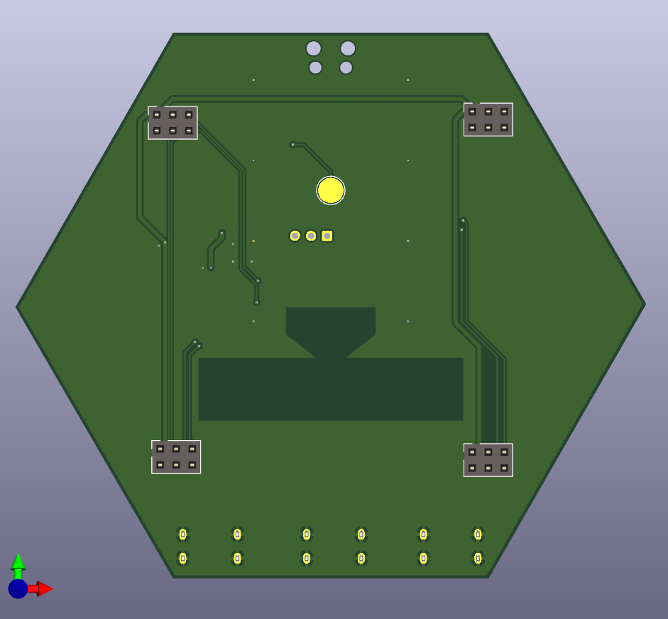
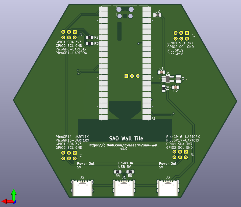
2 layers100 × 86.5 mmSao wall tile, the printed circuit board in 3D

Sao wall tile

bwasserm/sao-wall5

Wall tiles for mounting SAOs for display

Size
100 × 86.5 mm
Copper layers
2
Thickness
1.6 mm
Parts
19
Nets
42
Pads
165
Tracks, vias
180, 24
Pours
2
Routed
Yes
KiCad
KiCad 9.0 (file 20241229)
Created
8 Nov 2024
Updated
18 Jul 2025

Overview

Sao wall tile is an open-source printed circuit board by bwasserm, from the bwasserm/sao-wall repository on GitHub, published under the CERN-OHL-S-2.0 licence. It is a 2-layer board of 100 × 86.5 mm with 19 parts on 42 nets, routed with 180 tracks and 24 vias.

Its parts include 7 connectors, 5 resistors, 2 capacitors, 1 IC and 1 diode. It belongs with the lEDs and displays boards and the RP2040 boards of this library.

README

README.md

SAO Wall

Mount your SAOs on your wall for display.

Hackaday.io Page

Design Goals

  • Wall-mountable: that's the point
  • USB-powered: Ubiquitous and easy to acquire
  • Modular and Tileable: Easy to acquire arbitrary numbers to assemble and arrange however you want
  • Chainable: Can be connected together to share a power source
  • Simple: Can support SAOs that only require power without software
  • Smart: Can support interacting with I2C and GPIO on smart SAOs
  • Accessible: Keep component cost low and hand solderable for home assembly

Desgin trades/notes

  • USB provides 5V 3A without a PD controller, which should be enough
  • SAO 1.68bis spec specifies 250mA max per SAO, but most are smaller, so a 500mA 3.3V regulator seems reasonable for 4 SAOs. However it can be easily swapped for another at lower or higher current.
  • I tried board-edge connectors at first, but that really complicates making arbitrary layouts. Using cables makes that way easier, and USB-C connectors seem appropriate. Also, getting alignment correct of the connectors on the 60deg edges of the hexagon seemed more difficult.
  • One in and two out connectors is enough to make a power binary tree. I don't have any current monitoring yet, so be careful how many boards and SAOs get connected to the same supply.
  • 5cm per side is a nice round number, and keeps the tiles small, but big enough for the SAOs to have some space between them. Also, it should be plenty small enough for 0.3m USB cables between tiles, without being too tight or having too much extra slack to hide.
  • The Raspberry Pi Pico W is optional, for talking to smart SAOs (I2C or GPIO) and controlling the 3.3V regulator to turn them on and off. A Pico 2 W should also work. I wanted this to be compatible with firmware similar to the 2024 Supercon badge.
  • I picked Pico pins for 3 of the SAOs' GPIOs to be connected to UARTs on the Pico. It only has two UARTs, but at least those are options.
  • I wanted to put a current shunt on the 3.3V regulator to measure the load of the SAOs, but I didn't want to have the voltage drop on that rail, or add the op-amp to measure the tiny voltage difference to do that properly. At least not on this rev, but maybe a future rev.
  • No, its not going to be great RF performance from the Pico, but hopefully good enough.
  • The tiles can be arranged or connected in any order. All smart behavior is localized to the one tile, so it doesn't matter where it gets connected in the chain.

BOM

Digikey Shopping Cart: https://www.digikey.com/short/hjqzcd2n

Optional

Renders

Front Render Back Render

Attribution and feedback

If you make and distribute this, please add a reference back to me or this repo so people can know where it came from. If you make any new designs to integrate into this system, please let me know so everyone can learn about them. Thanks!

Parts

19
QtyValueFootprintReferences
4Conn_02x03_Odd_EvenConnector_PinSocket_2.54mm:PinSocket_2x03_P2.54mm_VerticalJ4, J5, J6, J7
24.7kResistor_SMD:R_0805_2012Metric_Pad1.20x1.40mm_HandSolderR2, R3
24.7uFCapacitor_SMD:C_0805_2012Metric_Pad1.18x1.45mm_HandSolderC1, C2
25.1KResistor_SMD:R_0805_2012Metric_Pad1.20x1.40mm_HandSolderR4, R5
2Power OutConnector_USB:USB_C_Receptacle_GCT_USB4125-xx-x_6P_TopMnt_HorizontalJ2, J3
11MResistor_SMD:R_0805_2012Metric_Pad1.20x1.40mm_HandSolderR1
14.7uHInductor_SMD:L_1008_2520Metric_Pad1.43x2.20mm_HandSolderL1
1D_SchottkyDiode_SMD:D_0805_2012Metric_Pad1.15x1.40mm_HandSolderD2
1Power InConnector_USB:USB_C_Receptacle_GCT_USB4125-xx-x_6P_TopMnt_HorizontalJ1
1RaspberryPi_Pico_WModule:RaspberryPi_Pico_W_SMD_HandSolderA1
1TestPointTestPoint:TestPoint_Pad_D4.0mmTP1
1~Package_TO_SOT_SMD:TSOT-23-5_HandSolderingU1

Similar boards

  • 2 layers43.9 × 27.7 mmTcd1304-4v, the printed circuit board in 3D

    Tcd1304-4v

    OpnTec/open-spectrometer-hardware

    Open source VIS spectrometer

    19 parts1.5k
  • 2 layers50 × 60 mmDebate Device, the printed circuit board in 3D

    Debate Device

    hackclub/OnBoard

    💡 Join 1,000 teenagers and make your first PCB with a $100 grant!

    19 parts915
  • 2 layers102.9 × 96.7 mmISA adapter, the printed circuit board in 3D

    ISA adapter

    polpo/picogus

    Emulation of ISA sound cards and CD-ROM on Raspberry Pi Pico (GUS, SB/Adlib, MPU-401, Tandy, CMS, Panasonic CD-ROM) with USB mouse/joystick support

    19 parts805
  • 2 layers60 × 39 mmPs2usb, the printed circuit board in 3D

    Ps2usb

    rasteri/HIDman

    Adapting USB devices to work on old computers

    19 parts432
  • 2 layers70.1 × 43.2 mmIaq device, the printed circuit board in 3D

    Iaq device

    nkitanov/iaq_board

    IAQ Board is a DIY (Do-It-Yourself) device for measuring internal air quality

    19 parts396
  • 2 layers80 × 80 mmGB BRK CPU G1, the printed circuit board in 3D

    GB BRK CPU G1

    Gekkio/gb-hardware

    Game Boy -related custom hardware by gekkio

    19 parts379CC-BY-4.0
  • 2 layers25.4 × 25.4 mmIna169, the printed circuit board in 3D

    Ina169

    Ardumower/ardumower

    Develop an open source robotic lawn mower (HW+SW reference platform)

    19 parts282
  • 2 layers58.4 × 28.6 mmNew rele, the printed circuit board in 3D

    New rele

    zmaker/arduino_cookbook

    gli sketch del nuovo progetto Arduino Cookbook e dei video di YouTube

    19 parts269

Questions

How big is the Sao wall tile PCB?

It measures 100 × 86.5 mm and has 2 copper layers, 1.6 mm thick.

What parts does the Sao wall tile use?

19 parts. The full list of its parts is on this page, with links to each part's symbol and footprint where PCBKit's library has them.

Where can I download the Sao wall tile KiCad files?

From the bwasserm/sao-wall repository on GitHub, at the commit this page was made from: the board is sao-wall-tile/sao-wall-tile.kicad_pcb and its schematic sao-wall-tile/sao-wall-tile.kicad_sch. PCBKit opens the board in the browser, with nothing to install.

Can I use the Sao wall tile design in my own project?

Its repository publishes it under the CERN-OHL-S-2.0 licence: you may reuse it on that licence's terms (keep the author's notice, and for a copyleft licence share your changes alike).