

UVLEDController
Since first coming across the ANT project, I've wanted to make one. However there are some esoteric hardware choices in the base project that seem to prioritize form over function and cost.
- Size
- 80 × 56 mm
- Copper layers
- 2
- Thickness
- 1.6 mm
- Parts
- 13
- Nets
- 30
- Pads
- 60
- Tracks, vias
- 38, 0
- Pours
- 1
- Routed
- Yes
- KiCad
- KiCad 6 (file 20211014)
- Created
- 15 Oct 2021
- Updated
- 10 Aug 2022
Overview
UVLEDController is an open-source printed circuit board by bvarner, from the bvarner/varnerized_ant_cpcbm repository on GitHub. It is a 2-layer board of 80 × 56 mm with 13 parts on 30 nets, routed with 38 tracks and 0 vias.
Its parts include 3 connectors, 1 resistor and 1 transistor. It belongs with the AVR (ATmega, ATtiny) boards of this library.
README
README.mdVarnerized ANT Compact PCB Maker
Since first coming across the ANT project, I've wanted to make one. However there are some esoteric hardware choices in the base project that seem to prioritize form over function and cost. As a hobbiest, my primary concerns are not asthetics as much as cost and component availability.
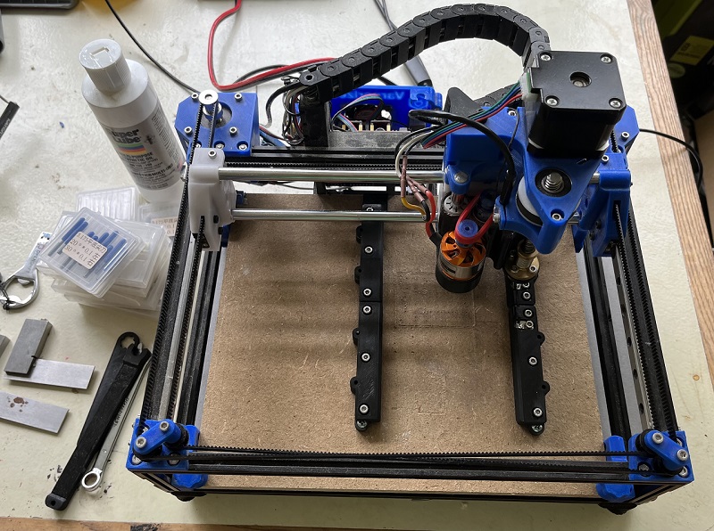
Varnerizations
- Created a parametric (parameterized) reimplemenation of the bridge & head in Fusion 360. Fusion Archive and STEP export included.
- 8MM Linear Rods & LM8UU linear bearings.
- Sacrificed 4mm of Y axis travel to allow for wall thicknesses to be reasonable with 15mm bores.
- Added 1mm to the height to the left-right bridge and center bridge, added 1mm separation betweeen centers of the x-axis rails.
- Bridge Core is now One Piece.
- Captive M3 Hex Nuts allow the use of (3) M3x30 and (3) M3x40 screws instead of the original BOM spec for (3) M3 threaded rods cut to length.
- Linear bearing holes are barely oversized, allowing for the M3x30 screws to act as compression mechanisms to hold the bearings.
- Expansion / Compression cut for linear bearings. M3 screws holding together the bridge act as compression points to hold the bearings snug.
- Use of sub-mini microswitches for limit-switches. No need to purchase specific orientation limit switch modules, especially when the connections to the grbl board aren't making use of pull resistors.
- NEMA17 Stepper Motors
- Reinforced COREXY Mounts based upon this design on Thingiverse eliminate the need for extra retainers from the thingiverse part.
- GT2 belt-driven Z-Axis. 140 Tooth 2GT-6 allows for swapping out gear ratios to adjust for different leadscrew pitches.
- TR8 Leadscrew (with 8mm pitch) for Z-Axis
- Remodeled and removed unnecessary holes from the bridge left and right.
- Belt holder holds a captive nut to secure it to the bridge.
- Easily Obtainable D2826 1000kv BLDC motor.
- 3d-printed TPU (shore 95A) drive belt.
- 3d-printed PolyCarbonate drive pulleys. (Eliminated the stop-collar on the spindle)
- Use of an open cable chain, and necessary mounts to the bridge & electronics case.
- Use of 40mm screws on the electronics case, further customizations to make it easier to fit panel-mount through-hole jacks.
- modified the electronics panel to use a rectangular switch and a XT-60H connector for power.
- 3d printed GT2 pulleys.
- I have since switched to machine pulleys, as I was diagnosing some movement precision issues. Changing to machined pulleys had no noticeable effect. My issues were elsewhere.
- PCBLock <-> Frame connection.
- Changed orientation of the contact strips to vertical -- allowing for more 'slop' between alignment in both the x, and z axis.
- Contact is no longer dependent upon the thickness of the spoil-board, so thinner / thicker board will still contact well.
- I used 4mm strips of 0.15mm thick nickel strip. (cut from an 8mm wide strip commonly used in 18650 battery packs)
Analysis and Evaulation Guidelines
In making my decisions about what to 'Varnerize' vs. purchase and stick to the plans I weighed things based upon:
- What's already in my component drawers or easily obtainable given current supply chain and production limitations. Prioritized functional available parts over form.
- What I can reasonably 3d-print and combine with something else already in my component drawers. Prioritized self fabrication over purchasing produced parts.
- Functional Accuracy. Modifications will prioritize accuracy over workable size. I was willing to reduce the work area. I didn't have to.
- Build cost.
Specific investigations undertaken
- NEMA17 steppers in place of the NEMA11s, and in the case of the head, in place of the NEMA 8. I've seen this top-mounted NEMA 11 modification which has supplied a surprising amount of 'idea fuel'.
- Bridge segmenting and joinery.
- Use of an Arduino Uno R3 + GRBL board instead of the STM32 based Arm board + GRBL board.
- 8mm Rods and LM8UU bearings instead of the 6mm rods and LM6UU bearings.
- 3d printable pulleys based around 683ZZ bearings. As of 10/2021 I was able to obtain a 20 pack of these bearings for $10. Sourcing the appropirate number of 16-tooth pulleys would have cost more than the 20 pack of bearings.
- Overhangs in some parts (which seem to be dimensionally important) should have 'snap-off' supports.
- Use of a TR8x8 leadscrew, along with a GT2 closed loop belt and pulley system for Z-Axis motion. I have a few of these belts laying around from converting my prusa-style printer to a Skelestruder extruder.
Purchased items I did not 'skimp' on:
- MakerBeam! I bought the starter kit, and the tee nuts. I did investigate printing the tee nuts and had workable facimilies printed with a 0.4mm nozzle but was not confident about the long-term use of the plastic tee-nuts.
- Linear rails. Experience from building 3d printers told me this was worth it.
- LM8UU Drylin Bushings. Because LM8UU ball bearings that are affordable are rubbish. I've been using drylin on my 3d printer for a year or so now, and it's so much quieter, and has so much less lash that it's just worth it.
- Mochu angular contact bearings & CL6-ER8M spindle.
Z-Axis Comparative Analysis
NEMA 8 ANT Head
The "Beta" NEMA 8 stepper head design uses a 1.8-degree, 18mN/m (0.018N/cm) holding torque stepper paired with a 4mm leadscrew with a 0.635mm pitch, equating to a 0.003175mm linear resolution per step. (0.635mm / 200 steps = 0.003175mm).
The default configuration is to set this to half-stepping, doubling the default ANT resolution to: (0.635 / 400) = 0.0015875mm
NEMA 17 Varnerized Head
I have on hand several 17HS4401 steppers, which are 1.8-degree, 42N/cm holding torque, and TR8x8 leadscrews with 8mm pitch and anti-backlash nuts. Un-reduced, this equates to a linear resolution of 0.04mm. (8 / 200 = 0.04mm)
In order to increase the resolution, I've selected a 16:52 gear ratio and 140 tooth GT2 timing belt (which I had on hand from building a Skelestruder extruder for my printer). This brings the effective resolution to: (8 / (200 * 3.25)) = 0.012307692mm
Enabling 1/4 stepping on the Z-axis motor brings this to: (8 / (200 * 3.25 * 4)) = 0.003076923mm -- slighty better than the half-stepped NEMA 8.
Enabling 1/8 stepping on the Z-axis will yield: (8 / (200 * 3.25 * 8)) = 0.001538462mm resolution -- on par with the half-stepped NEMA 8 head.
This equates to a theoretical steps/mm setting of: ~650 steps/mm
Assuming a loss of torque of 29% at the motor shaft (due to microstepping): At the mottor shaft, the motor provides 29.82N/cm of holding torque. (42 - (42 * 0.29)) At the lead-screw, this would be 3.25 times higher. (29.82 * 3.25) = 89.46N/cm
Conclusion:
With 1/8th microstepping, a 1:3.25 gear ratio, and an 8mm pitch leadscrew powered by a 17HS4401 NEMA17, we will exceed the repeatable resolution and torque of the ANT's NEMA8 head design. Furthermore this part selection will enable using parts I have on hand, cutting the cost to build the head unit considerably.
Original ANT Project resources
The Ant is a project to develop a CNC machine able to realize single and double-layered printed circuit boards.
The CNC machine is designed to achieve well-determined characteristics:
- Compact
- Low-cost
- Robust
- Scalable
- Easy to build
- Open License
To achieve these properties the following design principle have been adopted:
- Electrical, mechanical and electronics parts have been chosen to be small, low-cost and easily available on the open market or 3D printable
- Mechanical design has been oriented to minimize the space occupied by the components
- Mechanics has been designed to be robust and stress resistant
- Mechanics has been designed so that the external dimensions of the machine may be changed with a minimal change of pieces and no re-design needed.
- Mechanical and electrical designs have taken in account the assembling and disassembling operations, allowing to use easily available tools as screwdrivers, Allen wrenches and a solder for electrical contacts.
- The microcontroller board used to control the CNC machine is inexpensive (~15 $) but is equipped with a powerful STM32 processor and many peripherals.
- The machine control firmware can be loaded with almost no effort, since the microcontroller board has been chosen to have an on-board programmer.
- The control firmware is derived from GRBL v.0.9j, but it is also customized to achieve better performance, taking advantage of the powerful processor, and to be more flexible, since more configuration parameters and features have been added respect to the original firmware
The Ant is an open project, but if you feel like donating a small sum, you are very welcome. Just use the paypal button below.
Parts
13| Qty | Value | Footprint | References |
|---|---|---|---|
| 4 | MountingHole | MountingHole:MountingHole_3mm | H1, H2, H3, H4 |
| 3 | SW_Push | Button_Switch_THT:SW_PUSH_6mm | SW_DN1, SW_SEL1, SW_UP1 |
| 2 | Screw_Terminal_01x02 | TerminalBlock_Phoenix:TerminalBlock_Phoenix_PT-1,5-2-5.0-H_1x02_P5.00mm_Horizontal | J1-LED1, J2-PWR1 |
| 1 | 10k | Resistor_SMD:R_0805_2012Metric_Pad1.20x1.40mm_HandSolder | R1 |
| 1 | Arduino_Nano_v3.x | Module:Arduino_Nano | A1 |
| 1 | Conn_01x04_Male | Connector_PinHeader_2.54mm:PinHeader_1x04_P2.54mm_Horizontal | J3 |
| 1 | Q_NMOS_GDS | Package_TO_SOT_THT:TO-220-3_Horizontal_TabUp | Q1 |
Similar boards
- 2 layers40 × 20 mm

- 2 layers74.9 × 49.5 mm

- 2 layers35 × 29 mm

MagSpoofTC
samyk/magspoof
A portable device that can spoof/emulate any magnetic stripe, credit card or hotel card "wirelessly", even on standard magstripe (non-NFC/RFID) readers.
13 parts4.2k - 2 layers20.6 × 23.6 mm

AO-03 signal amplifier
fossasia/pslab-scripts
Pocket Science Lab - Scripts for Sensor Experiments
13 parts1.6kApache-2.0 - 2 layers47 × 35.6 mm

- 2 layers95 × 95 mm

Cube batteryboard
willem-pennings/balancing-cube
A cube that balances itself in a corner or edge using reaction wheels
13 parts1.1kGPL-3.0 - 2 layers15.2 × 20.3 mm

Pt100stick
VoronDesign/Voron-Hardware
Cool Hardware designed by the Voron Design group
13 parts1.1kGPL-3.0 - 2 layers53.9 × 23.2 mm

Buffer
hoglet67/RGBtoHDMI
Bare-metal Raspberry Pi project that provides pixel-perfect sampling of Retro Computer RGB/YUV video and conversion to HDMI
13 parts1kGPL-3.0
Questions
How big is the UVLEDController PCB?
It measures 80 × 56 mm and has 2 copper layers, 1.6 mm thick.
What parts does the UVLEDController use?
13 parts. The full list of its parts is on this page, with links to each part's symbol and footprint where PCBKit's library has them.
Where can I download the UVLEDController KiCad files?
From the bvarner/varnerized_ant_cpcbm repository on GitHub, at the commit this page was made from: the board is UVLEDController/UVLEDController/UVLEDController.kicad_pcb and its schematic CalibrationMilling/CalibrationMilling.kicad_sch. PCBKit opens the board in the browser, with nothing to install.
Can I use the UVLEDController design in my own project?
Its repository states no licence, so its author keeps all rights: ask bvarner before reusing the design.
{height=50 width=20}