2 layers116.8 × 30 mm
Type d
google/mozc-devices
Circuit diagrams and firmware source code for Gboard DIY keyboards
14 parts3kApache-2.0

 bvankampen/ledclock
Ledclock with NodeMCU ESP8266 - MAX7219 8x32 Led Display - RTC DS3221 - WIFI - NTP
Clock is an open-source printed circuit board by bvankampen, from the bvankampen/ledclock repository on GitHub, published under the CC0-1.0 licence. It is a 2-layer board of 128 × 32 mm with 14 parts on 30 nets, routed with 84 tracks and 2 vias.
Its parts include 5 resistors, 3 diodes, 2 connectors, 2 switches and 1 IC. It belongs with the lEDs and displays and radio and wireless boards and the ESP8266 boards of this library.
Led Clock based on a ESP8266. Built with VSCode and PlatformIO
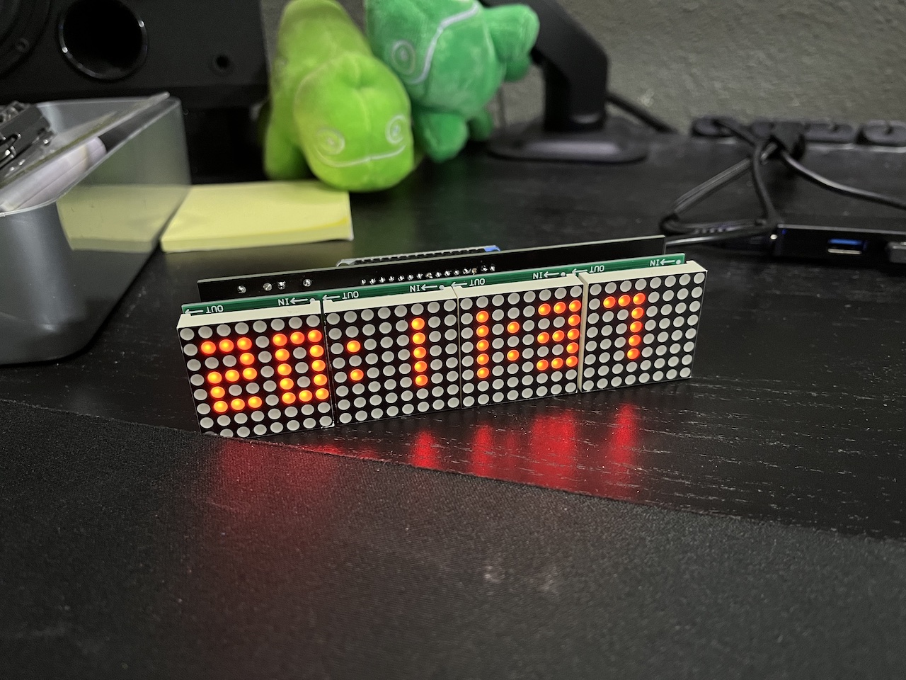
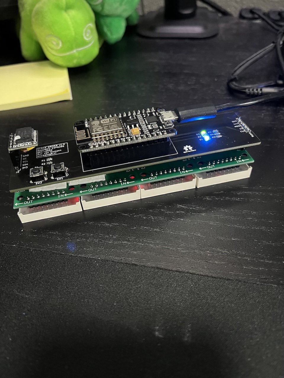
Included in Kicad folder
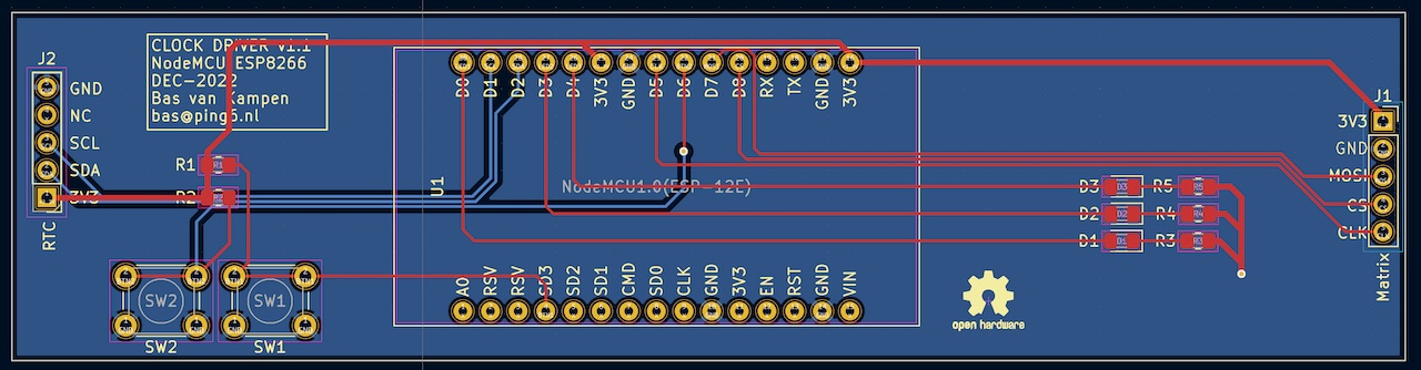
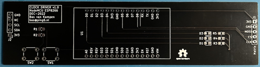
| Qty | Value | Footprint | References |
|---|---|---|---|
| 3 | 330 | Resistor_SMD:R_0805_2012Metric_Pad1.20x1.40mm_HandSolder | R3, R4, R5 |
| 3 | LED | LED_SMD:LED_0805_2012Metric_Pad1.15x1.40mm_HandSolder | D1, D2, D3 |
| 2 | 1K | Resistor_SMD:R_0805_2012Metric_Pad1.20x1.40mm_HandSolder | R1, R2 |
| 2 | Conn_01x05_Male | Connector_PinHeader_2.54mm:PinHeader_1x05_P2.54mm_Vertical | J1, J2 |
| 2 | SW_Push | Button_Switch_THT:SW_PUSH_6mm_H5mm | SW1, SW2 |
| 1 | NodeMCU1.0(ESP-12E) | ESP8266:NodeMCU_Amica | U1 |
The 13 most common of 14 parts.
It measures 128 × 32 mm and has 2 copper layers, 1.6 mm thick.
14 parts. The full list of its parts is on this page, with links to each part's symbol and footprint where PCBKit's library has them.
From the bvankampen/ledclock repository on GitHub, at the commit this page was made from: the board is Kicad/Clock.kicad_pcb and its schematic Kicad/Clock.kicad_sch. PCBKit opens the board in the browser, with nothing to install.
Its repository publishes it under the CC0-1.0 licence: you may reuse it on that licence's terms (keep the author's notice, and for a copyleft licence share your changes alike).
google/mozc-devices
Circuit diagrams and firmware source code for Gboard DIY keyboards


hackclub/OnBoard
💡 Join 1,000 teenagers and make your first PCB with a $100 grant!


Twotoz/C5VRX
Ultra-minimal, zero-CPU 5.8 GHz analog FPV video receiver using ESP32-C5 Wi-Fi 6 PHY MODEM_DIAG, BitScrambler WBFM demodulation & resistor DAC CVBS

