
2 layers150 × 48 mm

CPG is a mains-powered BleRiot node for controlling a circulation pump and a motorized 3-way or 4-way valve in floor-heating and radiator-heating circuits.
CPG is an open-source printed circuit board by burgrp, from the burgrp/bleriot-CPG repository on GitHub. It is a 2-layer board of 60 × 62 mm with 39 parts on 40 nets, routed with 186 tracks and 125 vias.
It is built around the HLK-PM03, PAN2110P0AA and BTA08S-600CW(KTP), with the WS2812B among its other parts. Its parts include 14 resistors, 6 capacitors, 6 ICs, 5 diodes and 3 connectors.


CPG is a mains-powered BleRiot node for controlling a circulation pump and a motorized 3-way or 4-way valve in floor-heating and radiator-heating circuits. It provides one switched output for the pump and two interlocked directional outputs for a reversible valve actuator.
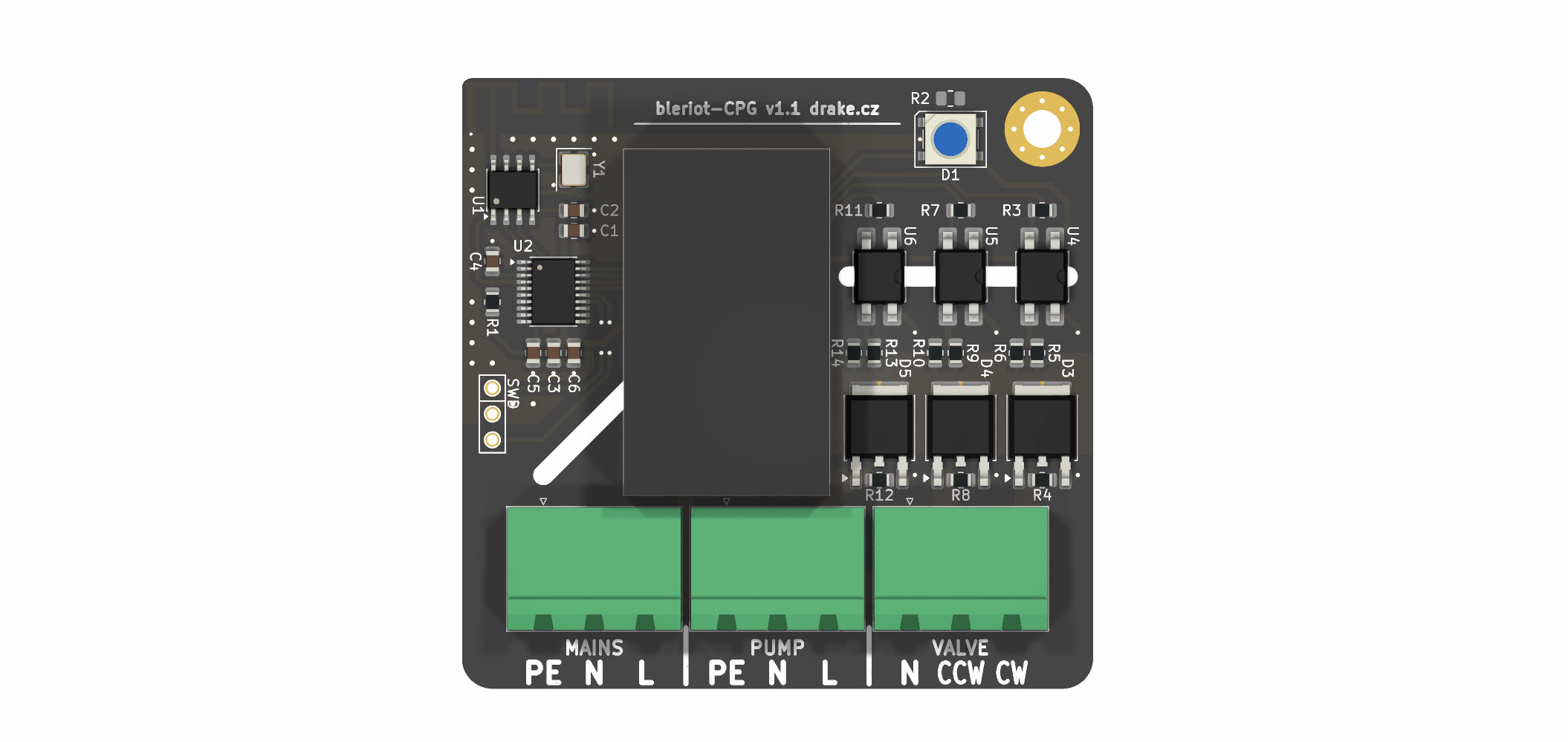
The board is intended for supervisory heating control. Its triac channels are on/off outputs; they are not phase-angle dimmers.
This arrangement supports common motorized mixing and diverting valves whose actuator has a neutral connection and separate CW and CCW live inputs. Confirm the actuator wiring and required reversal delay against its documentation.
Connector numbering follows the KiCad schematic and PCB footprints.
| Connector | Pin | Function |
|---|---|---|
J1 MAINS | 1 | Protective earth (PE) |
J1 MAINS | 2 | Neutral (N) |
J1 MAINS | 3 | Line (L) |
J2 VALVE | 1 | Valve neutral (N) |
J2 VALVE | 2 | Valve CCW switched live |
J2 VALVE | 3 | Valve CW switched live |
J3 PUMP | 1 | Protective earth (PE) |
J3 PUMP | 2 | Pump neutral (N) |
J3 PUMP | 3 | Pump switched live |
The three switched outputs use BTA08S-600CW triacs driven through MOC306x optotriacs. The pump channel is independent. Valve CW and CCW share a firmware interlock and must also be treated as mutually exclusive by any external controller.
| Tag | Name | Type | Meaning |
|---|---|---|---|
| 1 | vcw | bool | Valve clockwise output |
| 2 | vccw | bool | Valve counter-clockwise output |
| 3 | pump | bool | Circulation pump output |
| 5 | watchdog | int | Safety lease remaining time in seconds |
A value of 0 is off and 1 is on. During valve reversal both valve registers
report off until the dead time expires and the pending direction is energized.
Null and unknown writes are ignored, and other boolean values are normalized to
1. The former test-only LED register is retired.
The watchdog starts expired. Positive writes arm it for up to 60 seconds, and reads return the remaining whole seconds rounded up. Zero, negative, and NULL writes expire it immediately. While expired, pump and valve writes are ignored. Re-arming does not restore prior commands; the controller must send fresh output writes.
While the BleRiot link is online and the watchdog is armed, the status LED is automatic:
| Operating state | LED indication |
|---|---|
| All outputs off | Amber (0xa05000) |
| Pump on, no valve active | Green (0x00ff10) |
| Valve CW active | Red (0xff000a) |
| Valve CCW active | Blue (0x0020ff) |
Valve state has priority over pump state. During valve dead time, the LED shows
the pump indication when the pump is on and the idle indication otherwise.
An expired watchdog blinks blue (0x0000ff): 200 ms on and 800 ms off. An RF
offline link blinks orange (0xff3000) with the same timing and takes priority
over the watchdog indication.
When the watchdog expires, firmware switches the pump off and commands the
valve to its configured safe end. Valve reversal still uses the configured
break-before-make delay. WatchdogSafePositionCCW in
fw/cmd/dev/main.go selects the safe end: false selects
CW and true selects CCW. The current baked configuration selects CW. The
safe direction remains energized for actuators with internal end-limit
switching.
Independently, 30 seconds without a valid RF packet marks the link offline and applies the same safe state once. Startup remains all-off until the explicit watchdog is armed; output writes are ignored before then.
The firmware targets a PY32F030F1 MCU and controls a PAN2110 radio over three-wire SPI.
| Function | MCU pin | Schematic net | Behavior |
|---|---|---|---|
| Pump | PB4 | PUMP | Active-low output |
| Valve CCW | PB5 | VALVE_CCW | Active-low output |
| Valve CW | PB6 | VALVE_CW | Active-low output |
| Status LED | PB7 | LED | WS2812 data |
| PAN2110 CSN | PF3 | ~RF_CS | Active-low chip select |
| PAN2110 SCK | PA2 | RF_SCK | Clock |
| PAN2110 data | PA3 | RF_DATA | Bidirectional data |
At startup, firmware preloads PB4-PB6 high before changing them to outputs so the active-low optotriac inputs remain off. All three switched outputs start off. The status LED uses the offline heartbeat until a valid packet is received.
There is no mains zero-cross input. The MOC306x optotriacs shown in the schematic are zero-cross devices, so these channels provide on/off switching only.
board/ contains the KiCad schematic, PCB, BOM, and fabrication
outputs.fw/ contains the importable cpg TinyGo firmware and board-owned
build profile.fw/spec/ contains the configuration, register contract, chip,
and firmware manifest.fw/cmd/dev/ contains the local inventory and BleRiot CLI.burgrp/tinygo-drivers/ws2812
contains the reusable 24 MHz PY32 WS2812 driver.sub/hw-kicad/ is the shared KiCad library submodule.Initialize the hardware library after cloning:
git submodule update --init --recursiveThe firmware requires Go, TinyGo with the PY32 target support used by this project, GNU Arm Embedded binutils, and pyOCD with the Puya device pack.
cd fw
go test ./...
go run ./cmd/dev node gen --name cpg
go run ./cmd/dev node build --name cpg --disassembly
BleRiot generates a private entry point under .bleriot/firmware/cpg and calls
cpg.Run with the configured identity and spec.Config. The firmware profile
selects py32f030x8, scheduler-none, leaking GC, RTT serial, and a 100 kHz pyOCD
connection.
The first board was programmed through a WCH-Link at 100 kHz using an under-reset connection. With the board connected:
cd fw
go run ./cmd/dev node install-pack --name cpg
go run ./cmd/dev node build --name cpg --flash --rtt
Confirm the fitted MCU density before relying on the py32f030x8 target. Check
the physical board before using X1: older board revisions route the SWD header
labels to the wrong MCU pins and do not expose target voltage or reset.
The current firmware has been built, flashed, and exercised on the board:
End-to-end testing with the intended pump, valve actuator, heating controller, and RF hub is still required for each installation.
This design connects directly to hazardous mains voltage. Assembly, installation, testing, and enclosure work must be performed by suitably qualified people using applicable electrical codes and safe isolation practices.
Before deployment, independently verify at least:
After watchdog or RF timeout expiry, the pump switches off and the configured valve direction remains energized. Confirm that the actuator has suitable internal end-limit switching, and define maximum pump and valve run times for the installation.
Do not connect a pump, valve, or mains supply based only on the connector table; verify the assembled board against the schematic, PCB, and the equipment manufacturer's wiring documentation.
| Qty | Value | Footprint | References |
|---|---|---|---|
| 9 | 680R | Resistor_SMD:R_0805_2012Metric | R4, R5, R6, R8, R9, R10, R12, R13, R14 |
| 3 | 100n | Capacitor_SMD:C_0805_2012Metric | C2, C4, C5 |
| 3 | 270R | Resistor_SMD:R_0805_2012Metric | R3, R7, R11 |
| 3 | BTA08S-600CW | Package_TO_SOT_SMD:TO-252-2 | D3, D4, D5 |
| 3 | MOC306XMS | Package_DIP:SMDIP-4_W7.62mm | U4, U5, U6 |
| 2 | 1u | Capacitor_SMD:C_0805_2012Metric | C1, C3 |
| 1 | 10k | Resistor_SMD:R_0805_2012Metric | R1 |
| 1 | 16MHz | Crystal:Crystal_SMD_3225-4Pin_3.2x2.5mm | Y1 |
| 1 | 330R | Resistor_SMD:R_0805_2012Metric | R2 |
| 1 | 47u | Capacitor_SMD:C_0805_2012Metric | C6 |
| 1 | Antenna_Shield | RF_Antenna:Texas_SWRA117D_2.4GHz_Right | A1 |
| 1 | B72650M251K72 | Resistor_SMD:R_1210_3225Metric | RV1 |
| 1 | HLK-PM03 | Drake:HLK-PM01 | U3 |
| 1 | LED | LED_SMD:LED_0805_2012Metric_Pad1.15x1.40mm_HandSolder | D2 |
| 1 | MAINS | Connector_Phoenix_MSTB:PhoenixContact_MSTBA_2,5_3-G_1x03_P5.00mm_Horizontal | J1 |
| 1 | MountingHole | MountingHole:MountingHole_3.7mm_Pad_Via | H1 |
| 1 | PAN2110P0AA | Package_SO:SOIC-8_3.9x4.9mm_P1.27mm | U1 |
| 1 | PUMP | Connector_Phoenix_MSTB:PhoenixContact_MSTBA_2,5_3-G_1x03_P5.00mm_Horizontal | J3 |
| 1 | PY32F030F1xPx | Package_SO:TSSOP-20_4.4x6.5mm_P0.65mm | U2 |
| 1 | SWD | Drake:SWD | X1 |
| 1 | VALVE | Connector_Phoenix_MSTB:PhoenixContact_MSTBA_2,5_3-G_1x03_P5.00mm_Horizontal | J2 |
| 1 | WS2812B | LED_SMD:LED_WS2812B_PLCC4_5.0x5.0mm_P3.2mm | D1 |
It measures 60 × 62 mm and has 2 copper layers, 1.6 mm thick.
39 parts, built around the HLK-PM03, PAN2110P0AA, BTA08S-600CW(KTP) and WS2812B. The full list of its parts is on this page, with links to each part's symbol and footprint where PCBKit's library has them.
From the burgrp/bleriot-CPG repository on GitHub, at the commit this page was made from: the board is board/CPG.kicad_pcb and its schematic board/CPG.kicad_sch. PCBKit opens the board in the browser, with nothing to install.
Its repository states no licence, so its author keeps all rights: ask burgrp before reusing the design.


burgrp/bleriot-REG6
REG6 is a six-channel solid-state-relay controller built around a PY32F030 and PAN2110. This repository contains the KiCad hardware and a standalone TinyGo/BleRiot module under fw/ that exposes one integer percentage…


burgrp/bleriot
BleRiot is a compact request/response protocol for reading and writing named integer registers on low-power RF nodes. A Linux hub polls the nodes and bridges their registers to an external Registry service.

burgrp/bleriot-sense
BleRiot Sense is a compact single-sensor BleRiot node built around a PY32F003L16S6TU microcontroller and a PAN2110 long-range 2.4 GHz radio. Its sensor input is configured at assembly time for one of four uses:
