Skip to the content
PCBKitNew board
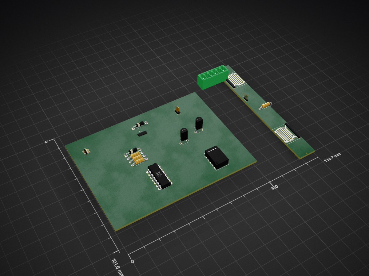
2 layers139.7 × 101.6 mmSwitch, the printed circuit board in 3D

Personal Home Automation Software Colaboration and Mycroft.AI interigation

Size
139.7 × 101.6 mm
Copper layers
2
Thickness
1.6 mm
Parts
17
Nets
68
Pads
70
Tracks, vias
0, 0
Routed
Not yet
KiCad
KiCad 5 (file 20171130)
Created
23 Feb 2019
Updated
20 Oct 2019

Overview

Switch is an open-source printed circuit board by builderjer, from the builderjer/ZiggyAI repository on GitHub, published under the GPL-3.0 licence. It is a 2-layer board of 139.7 × 101.6 mm with 17 parts on 68 nets.

It is built around the LM324. Its parts include 5 resistors, 4 connectors, 3 switches, 2 diodes and 2 transistors.

Main components

1

README

README.md

ZiggyAI

Personal Home Automation Software Colaboration and Mycroft.AI interrogation.

This is an always changing project. Check back often for updates.

Any ideas or comments are welcome!!

Table of Contents

  1. Concept
  2. House
  3. Upstairs
  4. Downstairs
  5. Garage
  6. Front Driveway
  7. Rear Driveway
  8. Lower Driveway
  9. Shop
Concept
  • The idea is to develop a smarthome with the lowest possible investment. I will be using several Raspberry pi's and Arduinos to do the light lifting, and an always on server to do the heavy part...I think.
  • Idealy, I would love to make my home self sufficent also, with solar and wind power charging a battery bank and LED lighting for energy efficient.
  • I want this home to be a true 'Smart Home'. This means that it will learn habbits of it's occupants, and adjust settings (at least the ones allowed in the settings) automaticly. This will require an array of different sensors including motion and light, temperature and humidity, door and window sensors, and maybe bluetooth for occupancy.
  • There are several items that are shared between rooms, such as sensor modules and switches. Each of these items will have it's own link and description.
House
  • My concept house is aprox. 3000 sq/ft with a main level, and a walk-out basement.
  • The main level consists of the kitchen, living area, two smaller bedrooms, an office, a full guest bath, and the master suite.
  • The walk-out basement has a wetbar area, a biliard room / game room, a small living area, a bathroom, small bedroom, a storage area, and the mechanical room.
  • The existing heating/cooling system is a combination forced air system. This limits climate control to a certain extent, but I have some ideas that may help with that.
  • All of the gas appliances have been converted to propane.
Upstairs
  • This is the main living area where most everything happens. It will be broken down into several smaller sections.

    • Kitchen
      • This is a large, but not huge kitchen that is being remodeled. The dimensions are aprox 12'x18'. The kitchen is equiped with new high effency GE appliances with a slate finish.

      • Electronics.

        • Idealy, there will be a main touchscreen interface mounted in a cabinet. This should be able to act as a callendar, a recipe book, and maybe a video interface for streaming Netflix or video calls.
        • My idea is to use an Android 10" tablet here. That way it can run a web page frontend and possably a Mycroft client. Maybe connect the tablet to the Raspberry Pi as a virtual desktop.
        • Raspberry Pi3.
          • This should connect to the main server webpage which maybe uses nodejs to interface back to the Arduinos.
          • I have also been looking into pymata, but have not made a decision yet. The advanatge to this would be there are several interfaces with several different languages. It also allows for the Arduinos to just run one specific firmware and allows the main interface to do the work.
          • I also want an instance of MycroftAI and all of it's awesome skills to help controll everything by voice commands.

Parts

17
QtyValueFootprintReferences
4RResistor_THT:R_Axial_DIN0207_L6.3mm_D2.5mm_P10.16mm_HorizontalR1, R2, R4, R5
2DDiode_THT:D_A-405_P10.16mm_HorizontalD1, D2
2Q_NPN_EBCPackage_TO_SOT_THT:TO-92L_WideQ1, Q2
2SW_Resistave_Touchpersonal:Resistave Touch ButtonSW1, SW2
1AZ850P2-xRelay_THT:Relay_DPDT_FRT5K1
1Conn_01x04_MaleConnector_PinHeader_1.00mm:PinHeader_1x04_P1.00mm_HorizontalJ2
1Conn_01x04_MaleConnector_PinHeader_1.00mm:PinHeader_1x04_P1.00mm_VerticalJ3
1Conn_02x04_Odd_EvenConnector_PinHeader_1.00mm:PinHeader_2x04_P1.00mm_VerticalJ1
1LM324Package_DIP:DIP-14_W7.62mm_LongPadsU2
1R_PHOTOConnector_Wire:SolderWirePad_1x02_P3.81mm_Drill0.8mmR3
1Screw_Terminal_01x06Connector_Phoenix_MC:PhoenixContact_MCV_1,5_6-G-3.5_1x06_P3.50mm_VerticalJ4

Questions

How big is the Switch PCB?

It measures 139.7 × 101.6 mm and has 2 copper layers, 1.6 mm thick.

What parts does the Switch use?

17 parts, built around the LM324. The full list of its parts is on this page, with links to each part's symbol and footprint where PCBKit's library has them.

Where can I download the Switch KiCad files?

From the builderjer/ZiggyAI repository on GitHub, at the commit this page was made from: the board is electronics/switch/switch.kicad_pcb. PCBKit opens the board in the browser, with nothing to install.

Can I use the Switch design in my own project?

Its repository publishes it under the GPL-3.0 licence: you may reuse it on that licence's terms (keep the author's notice, and for a copyleft licence share your changes alike).

Similar boards

  • 4 layers99 × 53.3 mmPSLab, the printed circuit board in 3D

    PSLab

    fossasia/pslab-hardware

    PSLab Hardware Design and Schematics https://pslab.io

    199 parts1.7kApache-2.0
  • 2 layers36.8 × 34.7 mmTinylab proto1, the printed circuit board in 3D

    Tinylab proto1

    espotek-org/Labrador

    EspoTek Labrador is a USB device that transforms your PC or smartphone into a fully-featured electronics lab. This repo holds all of the source code!

    79 parts1.2k
  • 4 layers82.6 × 82.5 mmJumperless2, the printed circuit board in 3D

    Jumperless2

    Architeuthis-Flux/Jumperless

    A jumperless breadboard

    208 parts914
  • 2 layers231.1 × 106.7 mmSnark barker, the printed circuit board in 3D

    Snark barker

    schlae/snark-barker

    A 100% compatible replica of the famed SB 1.0 sound card

    199 parts687
  • 4 layers82.6 × 82.6 mmJumperlessV5r8, the printed circuit board in 3D

    JumperlessV5r8

    Architeuthis-Flux/JumperlessV5

    The next generation jumperless breadboard

    650 parts332
  • 4 layers72.4 × 95.3 mmDingoPDM, the printed circuit board in 3D

    DingoPDM

    corygrant/dingoPDM

    Hardware - dingoPDM is an open source, affordable automotive PDM (Power Distribution Module). Pre-assembled and tested units are available or the design can be used to build a DIY version.

    156 parts128MIT
  • 2 layers191.5 × 76 mmPcb project, the printed circuit board in 3D

    Pcb project

    CrashOverride85/zc95

    4 channel EStim box inspired by the mk312bt, with Lua scripting support

    337 parts117GPL-3.0
  • 4 layers292.1 × 88.3 mmSnark barker mca, the printed circuit board in 3D

    Snark barker mca

    schlae/snark-barker-mca

    A Sound Blaster compatible sound card for Micro Channel bus computers

    177 parts69