2 layers172.5 × 392 mm

 btrinite/robocars_hat_hw2
The Hat combines : - LM2596 or xl4005 DSN5000 based DC/DC converter to power everything from a single battery (7-15V, NiMh or LiPo 2S/3S), through GPIO or through dedicated connector.
RobocarsHat is an open-source printed circuit board by btrinite, from the btrinite/robocars_hat_hw repository on GitHub, published under the MIT licence. It is a 2-layer board of 65 × 56 mm with 39 parts on 31 nets, routed with 503 tracks and 12 vias.
It is built around the LM2596S-5.0, BSS138 and WS2812B. Its parts include 11 resistors, 6 connectors, 2 ICs, 2 transistors and 1 capacitor. It belongs with the AVR (ATmega, ATtiny) boards of this library.


This Hat is designed for Raspberry Pi 3/4, Jetson Nano or any other SBC implementing the well known 'rpi' GPIO connector. This Hat provides various interfaces between SBC (Single Board Controler) and hardware to easely build an autonomous small scale RC-style car. A typical example of such build is the Donkey car
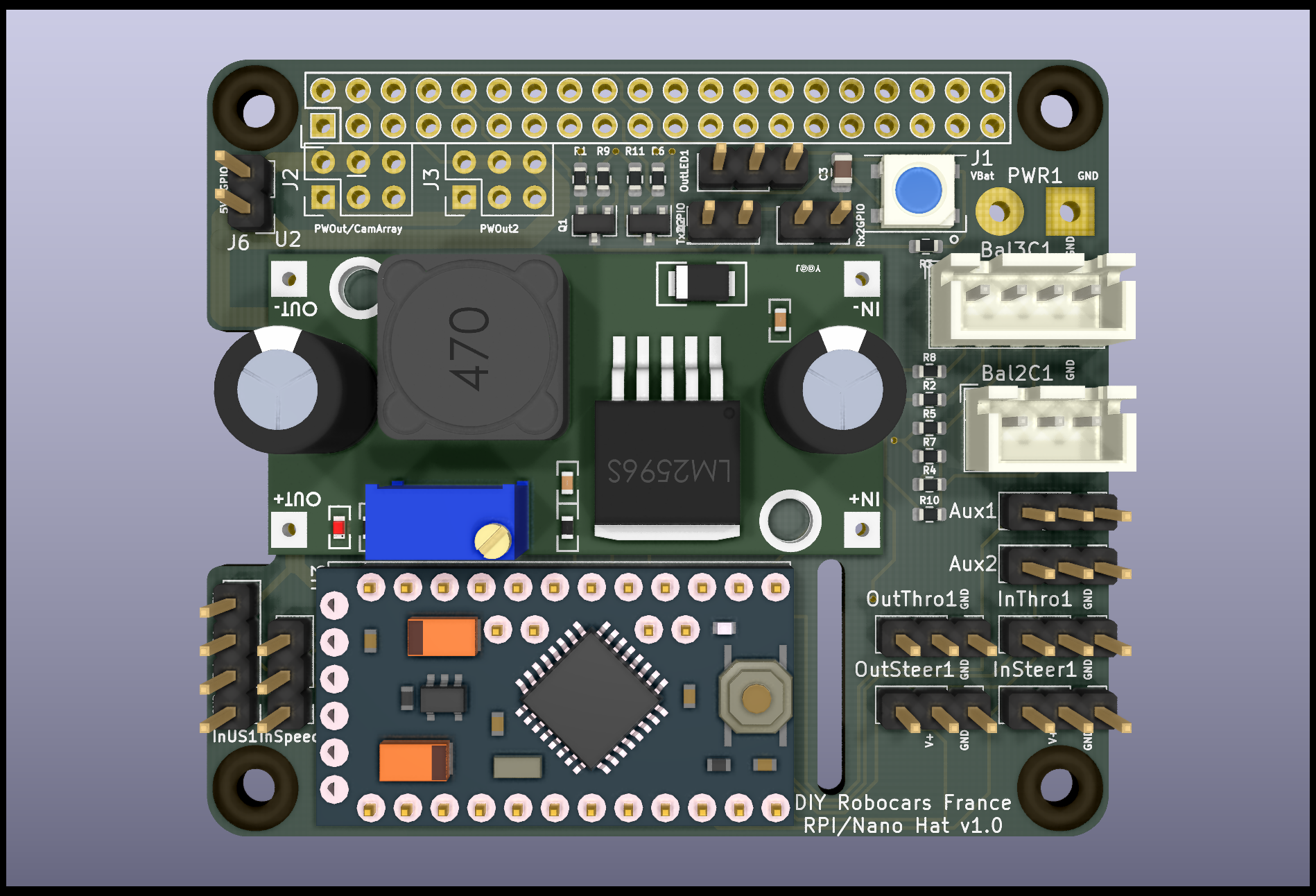
The Hat combines :
The Hat has the following I/O :
The follwing jumpers are provided for convenience :
A typical wiring of the Hat is shown below :
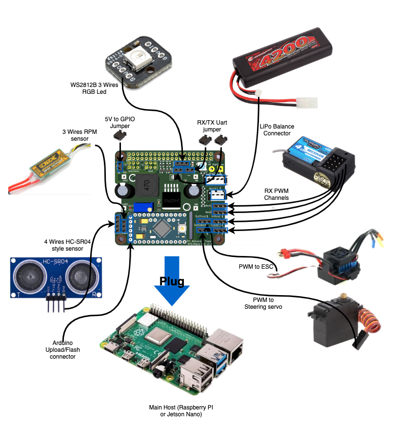
Consult Schematics.pdf
Hat does not provide power supply through PWM Inputs/Outpus. It is usualy duty of the motor controller (ESC) which feature a BEC. This is to avoid mixing logic and actuators on the same power source. It means that as long as ESC is not connected and switchded on, Servo and RX Receiver will not be powered.
In the current implementation,
First, as soon as the Hat is powered, a default Idle signal is driven (1,5ms pulse width) This default idle signal could differ from the one you could have when doing calibration.
Second, many ESC will autocalibrate to this idle signal at startup time (when switched on)
If you are in that case, it is recommanded to switch on the ESC only after the main application is up and running.
Third party components libraries needed :
Firmware to upload to the Arduino ca be found here
To flash firmware, you need to connect a 5V FTDI adaptor featuring DTR signal and use Arduino IDE to flash/upload the content. Do not forget to solder Pin header connector on Arduino Pins dedicated for uploading/flash purpose. You can find more informations here
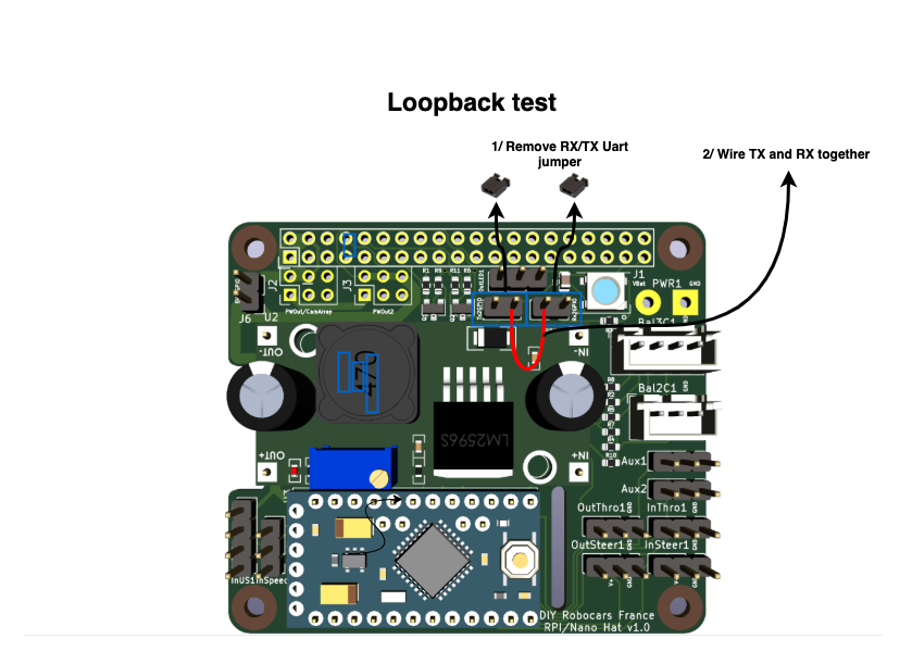
SimpleSerial protocol messages that carry throttle and steering are almost symetrical. Thus, if you loopback the serial comunication (RX wired to TX), the Hat will work in loopback mode. Throttle/Steering orders received from RX Receiver will be used to drive Throttle/Steering output.
Loopback mode is achieved by :
This is illsutrated below :
Modified Donkeycar software with integration of the DIYRobocarsFr Hat is available here
| Qty | Value | Footprint | References |
|---|---|---|---|
| 8 | Conn_01x03_Male | Connector_PinHeader_2.54mm:PinHeader_1x03_P2.54mm_Vertical | Aux1, Aux2, InSpeed1, InSteer1, InThro1, OutLED1, OutSteer1, OutThro1 |
| 4 | RPi_Hat:RPi_Hat_Mounting_Hole | , , , | |
| 4 | 10K | Resistor_SMD:R_0603_1608Metric | R1, R6, R9, R11 |
| 3 | 100k | Resistor_SMD:R_0603_1608Metric | R2, R5, R8 |
| 3 | 10k | Resistor_SMD:R_0603_1608Metric | R4, R7, R10 |
| 2 | BSS138 | Package_TO_SOT_SMD:SOT-23 | Q1, Q2 |
| 2 | Conn_01x02_Male | Connector_PinHeader_2.54mm:PinHeader_2x01_P2.54mm_Vertical | J4, J5 |
| 1 | 100nF | Capacitor_SMD:C_0805_2012Metric | C3 |
| 1 | 150R | Resistor_SMD:R_0603_1608Metric | R3 |
| 1 | Arduino_Pro_Mini | Arduino:Arduino_Pro_Mini | U3 |
| 1 | Conn_01x02_Male | Connector_PinHeader_2.54mm:PinHeader_1x02_P2.54mm_Vertical | J6 |
| 1 | Conn_01x04_Male | Connector_PinHeader_2.54mm:PinHeader_1x04_P2.54mm_Vertical | InUS1 |
| 1 | LM2596 | LM2596:YAAJ_DCDC_StepDown_LM2596 | U2 |
| 1 | PWOut | Pin_Headers:Pin_Header_Straight_2x03_Pitch2.54mm | J3 |
| 1 | PWOut/Camarray | Pin_Headers:Pin_Header_Straight_2x03_Pitch2.54mm | J2 |
| 1 | PWR1 | Connector_Wire:SolderWirePad_1x02_P5.08mm_Drill1.5mm | PWR1 |
| 1 | PWR2 | Connector_JST:JST_XH_B3B-XH-A_1x03_P2.50mm_Vertical | Bal2C1 |
| 1 | PWR3 | Connector_JST:JST_XH_B4B-XH-A_1x04_P2.50mm_Vertical | Bal3C1 |
| 1 | RPi_GPIO | RPi_Hat:Pin_Header_Straight_2x20 | J1 |
| 1 | WS2812B | LED_SMD:LED_WS2812B_PLCC4_5.0x5.0mm_P3.2mm | D1 |
It measures 65 × 56 mm and has 2 copper layers, 1.6 mm thick.
39 parts, built around the LM2596S-5.0, BSS138 and WS2812B. The full list of its parts is on this page, with links to each part's symbol and footprint where PCBKit's library has them.
From the btrinite/robocars_hat_hw repository on GitHub, at the commit this page was made from: the board is RobocarsHat.kicad_pcb. PCBKit opens the board in the browser, with nothing to install.
Its repository publishes it under the MIT licence: you may reuse it on that licence's terms (keep the author's notice, and for a copyleft licence share your changes alike).

willem-pennings/balancing-cube
A cube that balances itself in a corner or edge using reaction wheels


jacob-jarick/esp-solar-contoller
esp8266 and esp32 based solar controllers targetting fronius inverter users

jelgerlemmens/ToyTrainESP32
ESP32-C3 WiFi DCC decoder firmware and KiCad PCB design


Minh-Nguyen-CEAA/PCB-Capstone-Project-Kicad
Design and development of a 24VDC motor control board using STM32F411, integrated with ESP32 communication, ICM-20948 IMU sensor, UWB positioning module, and dual buck converters (5V & 3.3V) for embedded robotic…
