2 layers67.4 × 44.8 mm

 bseibold/letitrain5
An ESP32 board intended for use with TL-136 level sensors
Letitrain is an open-source printed circuit board by bseibold, from the bseibold/letitrain repository on GitHub, published under the MIT licence. It is a 2-layer board of 71 × 51 mm with 47 parts on 50 nets, routed with 221 tracks and 69 vias.
It is built around the ESP32-WROOM-32D, MCP9700B-E/TT and OP07, with the BSS84 and P4SMAJ30CA among its other parts. Its parts include 16 resistors, 11 capacitors, 9 connectors, 4 ICs and 1 diode. It belongs with the sensors and measurement boards and the ESP32 boards of this library.


An ESP32 board intended for use with TL-136 level sensors
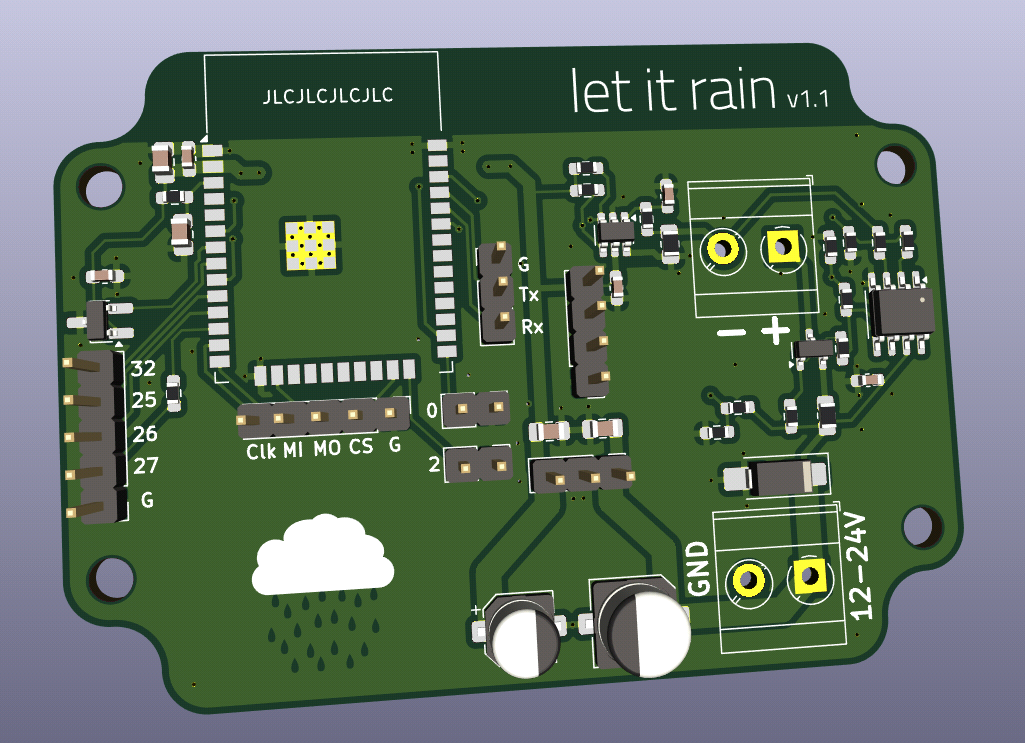
Version 1 was built and is running well.
The sensor officially requires 24V, but in practice it runs well down to about 7V. An op-amp is used to limit the current through the sensor and protect the ADC in case of a short-circuit. The bias current of the op-amp has a small but measureable effect, however the voltage measured by the ADC is still very linear to the current through the sensor.
The board can be used with ESPHome, see esphome.yaml for an example configuration.
1x TL-136 differential pressure level sensor
1x ESP32-WROOM-32x, can be any variant with the same footprint
1x MCP3421 ADC converter
1x OP07 Operational Amplifier
1x MCP9700B temperature sensor (optional)
1x DC-DC module with 780x compatible pins and 3.3V output. Must support 12-18V input
MLCC capacitors 0603, X5R or X7R, at least 6.3V
MLCC capacitors 0603, X5R or X7R, at least 25V (better 50V)
1x Polymer capacitor 5.0mm, at least 6.3V, 22µF (C10)
1x Polymer capacitor 6.3mm, at least 25V (better 50V), 10µF (C11)
1x Bidirectional TSV diode, SMA, voltage slightly above max. supply voltage (D1, optional)
1x Pin header 0,1" 1x3 Pins (J3)
1x BSS84 P-Channel Enhancement MOSFET (Q1)
8x Resistor 0603, 10kOhm (R1, R3, R4, R9, R10, R11, R12, R15)
2x Resistor 0603, 47kOhm (R2, R13)
3x Resistor 0603, 1kOhm (R5, R6, R7)
1x Resistor 0805, 100Ohm, high precision (R8)
1x Resistor 0805, 33Ohm (R14)
Optional pin headers are omitted. They are intended for later reuse of spare PCBs.
The enclosure is an RL6115 from Hammond Manufacturing.
| Qty | Value | Footprint | References |
|---|---|---|---|
| 8 | 10k | Resistor_SMD:R_0603_1608Metric_Pad0.98x0.95mm_HandSolder | R1, R3, R4, R9, R10, R11, R12, R15 |
| 5 | 100n | Capacitor_SMD:C_0603_1608Metric_Pad1.08x0.95mm_HandSolder | C1, C3, C5, C6, C7 |
| 4 | MountingHole | MountingHole:MountingHole_3.2mm_M3 | H1, H2, H3, H4 |
| 3 | 1k | Resistor_SMD:R_0603_1608Metric_Pad0.98x0.95mm_HandSolder | R5, R6, R7 |
| 2 | 10u | Capacitor_SMD:C_0805_2012Metric_Pad1.18x1.45mm_HandSolder | C4, C9 |
| 2 | 1u | Capacitor_SMD:C_0805_2012Metric_Pad1.18x1.45mm_HandSolder | C2, C8 |
| 2 | 47k | Resistor_SMD:R_0603_1608Metric_Pad0.98x0.95mm_HandSolder | R2, R13 |
| 2 | Conn_01x02 | Connector_PinHeader_2.54mm:PinHeader_1x02_P2.54mm_Vertical | J8, J9 |
| 2 | Conn_01x05 | Connector_PinHeader_2.54mm:PinHeader_1x05_P2.54mm_Vertical | J1, J2 |
| 2 | Screw_Terminal_01x02 | TerminalBlock_MetzConnect:TerminalBlock_MetzConnect_Type073_RT02602HBLU_1x02_P5.08mm_Horizontal | J4, J7 |
| 1 | 100 | Resistor_SMD:R_0805_2012Metric_Pad1.20x1.40mm_HandSolder | R8 |
| 1 | 10u | Capacitor_SMD:CP_Elec_6.3x5.8 | C11 |
| 1 | 220 | Resistor_SMD:R_0603_1608Metric_Pad0.98x0.95mm_HandSolder | R16 |
| 1 | 22u | Capacitor_SMD:CP_Elec_5x5.8 | C10 |
| 1 | 33 | Resistor_SMD:R_0805_2012Metric_Pad1.20x1.40mm_HandSolder | R14 |
| 1 | BSS84 | Package_TO_SOT_SMD:SOT-23 | Q1 |
| 1 | Conn_01x03 | Connector_PinHeader_2.54mm:PinHeader_1x03_P2.54mm_Vertical | J3 |
| 1 | Conn_01x03_Pin | Connector_PinHeader_2.54mm:PinHeader_1x03_P2.54mm_Vertical | J6 |
| 1 | Conn_01x04 | Connector_PinHeader_2.54mm:PinHeader_1x04_P2.54mm_Vertical | J5 |
| 1 | ESP32-WROOM-32D | RF_Module:ESP32-WROOM-32D | U2 |
| 1 | MCP3421A0T-ECH | Package_TO_SOT_SMD:SOT-23-6 | U3 |
| 1 | MCP9700B | Package_TO_SOT_SMD:SOT-23_Handsoldering | U1 |
| 1 | NetTie_2 | NetTie:NetTie-2_SMD_Pad0.5mm | NT1 |
| 1 | OP07 | Package_SO:SO-8_3.9x4.9mm_P1.27mm | U4 |
| 1 | P4SMAJ30CA | Diode_SMD:D_SMA_Handsoldering | D1 |
It measures 71 × 51 mm and has 2 copper layers, 1.6 mm thick.
47 parts, built around the ESP32-WROOM-32D, MCP9700B-E/TT, OP07 and BSS84. The full list of its parts is on this page, with links to each part's symbol and footprint where PCBKit's library has them.
From the bseibold/letitrain repository on GitHub, at the commit this page was made from: the board is letitrain.kicad_pcb and its schematic letitrain.kicad_sch. PCBKit opens the board in the browser, with nothing to install.
Its repository publishes it under the MIT licence: you may reuse it on that licence's terms (keep the author's notice, and for a copyleft licence share your changes alike).


SP6GK/Forte-600-HF-RF-Amplifier
Project of 600 W LDMOS amlifier based on 2xMRF300.


bash227/ECG-Motor-Control-Power-Management-PCB
A multi-function PCB integrating biomedical signal acquisition (ECG), DC motor control, and advanced power management for wearable applications.