2 layers40.6 × 110 mm
Europi surface mount
Allen-Synthesis/EuroPi
EuroPi: A reprogrammable Eurorack module based on the Raspberry Pi Pico
92 parts584CC0-1.0

 bricktrooper/Spectrum8
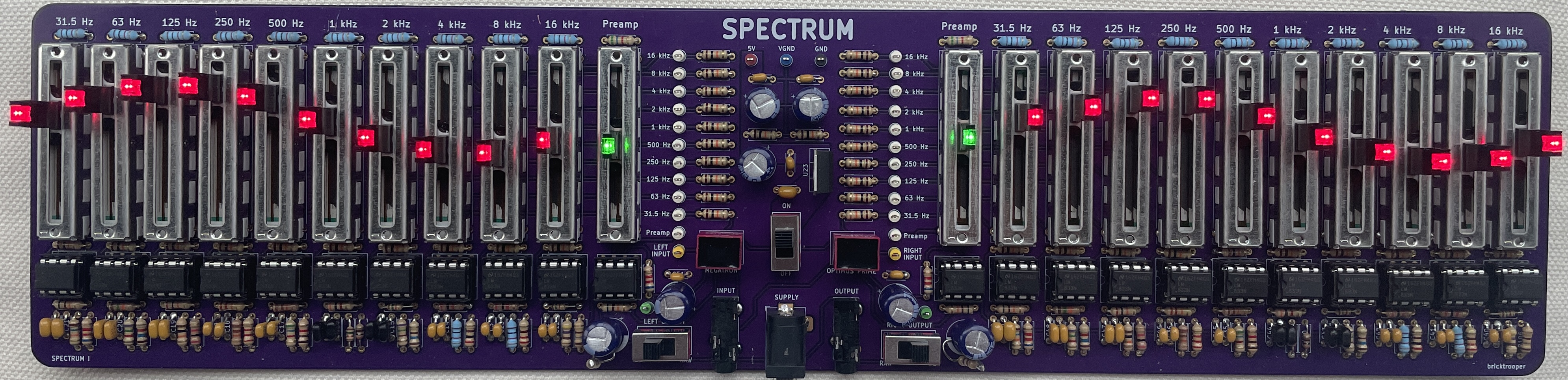
10-band stereo graphic equalizer circuit.
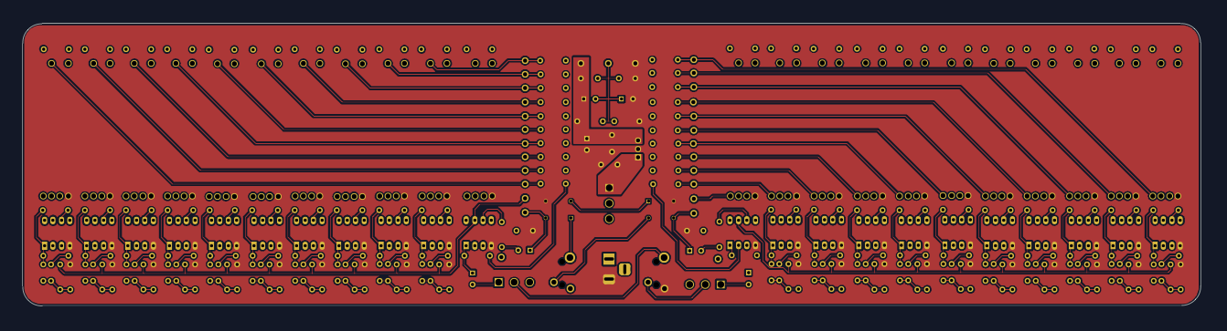
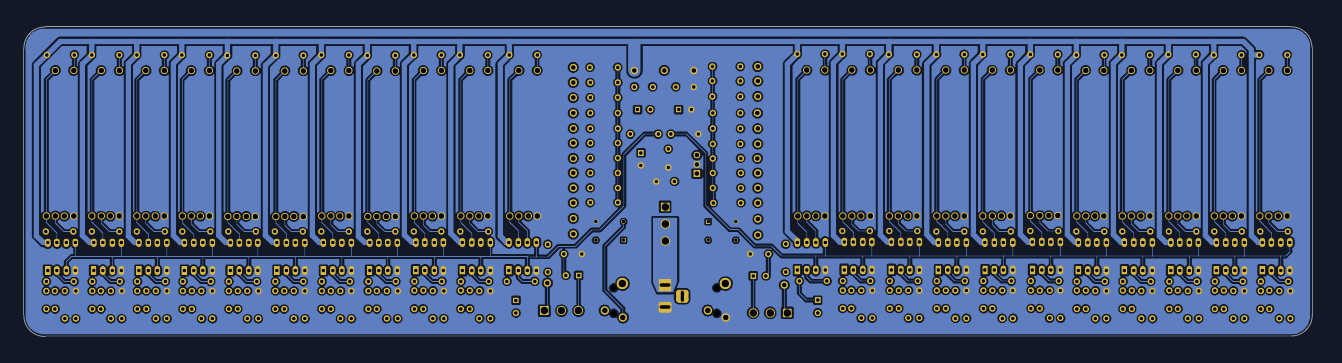
Spectrum is an open-source printed circuit board by bricktrooper, from the bricktrooper/Spectrum repository on GitHub. It is a 2-layer board of 354 × 85 mm with 265 parts on 148 nets, routed with 1,138 tracks and 0 vias.
It is built around the L7805 and SP-70. Its parts include 130 resistors, 53 capacitors, 23 ICs, 3 connectors and 3 switches.

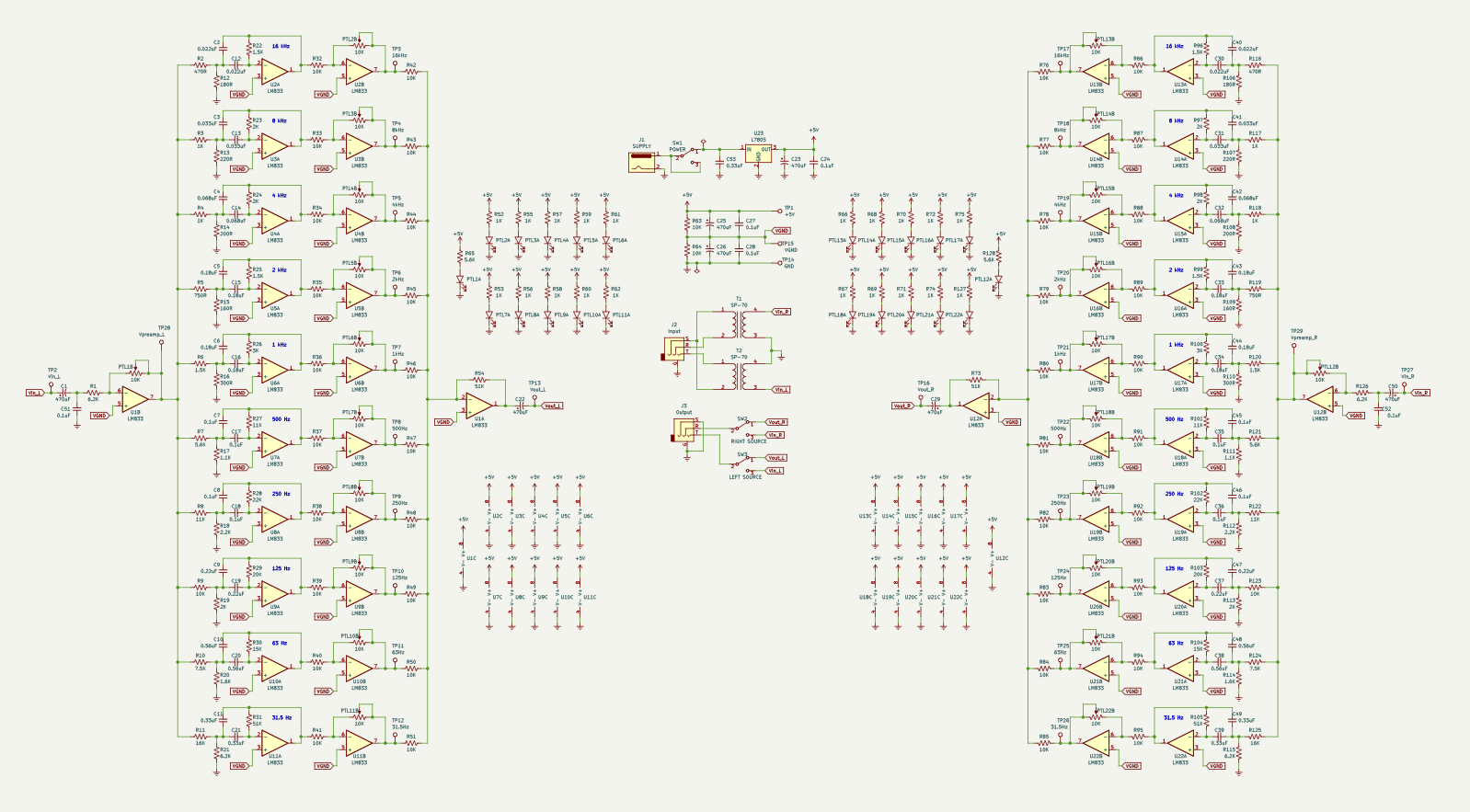
Spectrum is a 10-band stereo graphic equalizer circuit. It uses active band pass filters in a multiple feedback configuration. Each band can be individually amplified or attenuated using linear potentiometers. The circuit requires an external power source of at least 5 V at 250 mA.
A graphic equalizer is a piece of audio equipment that isolates different ranges of frequencies from an audio signal. These ranges can then be individually amplified (boosted) or attenuated (cut). The modified signals are mixed back together into a single audio signal which appears at the output. The resulting signal is the same audio but with each frequency range adjusted with a desired gain.
The most basic form of electrical audio signals is "mono". This is a single audio signal that plays through all the speakers. "Stereo" uses two separate audio signals that differ slightly but can be used to give the perception of spatial audio. Typically, the signals are used to drive separate "left" and "right" speakers. A graphic equalizer only operates on a single mono signal. Spectrum effectively uses two identical mono circuits to modify both channels of stereo audio. The resulting output can be played through stereo headphones. The circuit must be powered by an external wall adapter or any other 5 V source that can supply approximately 250 mA of current.
Spectrum uses a 5 V power supply that is regulated by an L7805 LDO. Traditionally, operational amplifiers use a bipolar supply of +VDD and -VDD, with the ground point of the signal being 0 V. This is not possible with a single supply. Therefore, Spectrum raises the ground point to a virtual ground of (VDD / 2), or 2.5 V. The op amps are supplied by 5 V and sink to 0 V (GND). This provides 2.5 V of signal swing, which is enough for driving headphones to a considerable volume. To drive large speakers, a separate amplifier should be used. Capacitive coupling is used to inject an AC audio signal into a 2.5 V bias and decouple the bias at the output headphone jack.
The preamplifier's job is to drive the rest of the circuit, effectively isolating the input resistance of the circuit from the audio source. This is important because headphone jack outputs cannot drive very high impedances. The preamplifer is also capable of amplifying or attenuating the input signal. Amplification may be required if the input source is too quiet, while attenuation can be used to reduce distortion in the output signal. The input to the preamplifier is further isolated using a 1:1 audio transformer. This prevents the ground of the circuit from creating a ground loop through the audio cable, which creates an undesirable humming noise due to the oscillation of the AC mains voltage. The preamplifier is implemented as a simple inverting amplifier. A capacitor is used at the input to strip out any existing DC voltage and the output signal is re-biased at the virtual ground point. A potentiometer is used in the feedback resistance to amplify or attenuate the signal linearly.
The core circuit of a graphic equalizer is the band pass filter, which isolates a range of frequencies. Different resistor and capacitor values are used to achieve different cutoff frequencies over the bass, mid, and treble ranges. Spectrum uses 10 filters for each audio channel. The centre frequencies are chosen based on standard octaves:
These are active filters that used op amps in the multiple-feedback configuration, which allows the cutoff frequency to be changed without affecting the gain of the centre frequency. The gain of all the filters have been adjusted so that the entire audio range has a flat gain response when the filter outputs are mixed back together. Each individual filter has a DC gain of 1 V/V, with the exception of 31.5 Hz and 16 kHz, which have a gain of 1.6 V/V. A quality factor of Q = 1.7 is used for all filters. The component selection is as follows:
-------------------------------------------------------------------------------------------------------------------
| BAND    | ERROR      | C          | R1         | R2         | R3         | f          | Q          | A          |
-------------------------------------------------------------------------------------------------------------------
| 31.5 Hz | 0.816      | 0.33 uF    | 16 K       | 51 K       | 6.2 K      | 31.948 Hz  | 1.689      | 1.594 V/V  |
| 63 Hz   | 0.745      | 0.56 uF    | 7.5 K      | 15 K       | 1.6 K      | 63.902 Hz  | 1.686      | 1.000 V/V  |
| 125 Hz  | 0.709      | 0.22 uF    | 10 K       | 20 K       | 2 K        | 125.302 Hz | 1.732      | 1.000 V/V  |
| 250 Hz  | 0.709      | 0.1 uF     | 11 K       | 22 K       | 2.2 K      | 250.604 Hz | 1.732      | 1.000 V/V  |
| 500 Hz  | 1.204      | 0.1 uF     | 5.6 K      | 11 K       | 1.1 K      | 500.462 Hz | 1.729      | 0.982 V/V  |
| 1 kHz   | 1.328      | 0.18 uF    | 1.5 K      | 3 K        | 0.3 K      | 1.021 kHz  | 1.732      | 1.000 V/V  |
| 2 kHz   | 0.467      | 0.18 uF    | 0.75 K     | 1.5 K      | 0.16 K     | 1.988 kHz  | 1.686      | 1.000 V/V  |
| 4 kHz   | 1.078      | 0.068 uF   | 1 K        | 2 K        | 0.2 K      | 4.054 kHz  | 1.732      | 1.000 V/V  |
| 8 kHz   | 0.812      | 0.033 uF   | 1 K        | 2 K        | 0.22 K     | 8.031 kHz  | 1.665      | 1.000 V/V  |
| 16 kHz  | 0.916      | 0.022 uF   | 0.47 K     | 1.5 K      | 0.18 K     | 16.373 kHz | 1.697      | 1.596 V/V  |
-------------------------------------------------------------------------------------------------------------------Each band pass filter is followed by an inverting amplifier, which has adjustable gain via a potentiometer in the feedback path. This allows the user to individually boost or cut different frequency ranges. At the potentiometer neutral point, the gain of the band amplifier is 0.5 V/V, meaning that each band can be attenuated down to 0 V/V or boosted up to 1 V/V, which is the gain of the band pass filters. Any further amplification must be provided from the audio source and the preamplifier. Due to band overlap, the actual realized gain is slightly higher or lower than in theory. This is a tradeoff between selectivity and gain accuracy.
The mixer is a summing amplifier that re-combines all the band signals back into a single audio signal. It has a fixed gain of 5 V/V, and the output signal can directly drive low-impedance headphones. The output signal runs through a large capacitor to cut out the virtual ground DC bias to avoid damaging the headphone speaker coils. This turns the signal into an AC waveform with a GND as the reference point.
| Qty | Value | Footprint | References |
|---|---|---|---|
| 44 | 10K | Resistor_THT:R_Axial_DIN0207_L6.3mm_D2.5mm_P7.62mm_Horizontal | R32, R33, R34, R35, R36, R37, R38, R39, R40, R41, R42, R43, R44, R45, R46, R123 +28 |
| 24 | 1K | Resistor_THT:R_Axial_DIN0207_L6.3mm_D2.5mm_P7.62mm_Horizontal | R3, R4, R52, R53, R55, R56, R57, R58, R59, R60, R61, R62, R66, R117, R118, R127 +8 |
| 22 | 10K | Bourns_PTL:PTL30 | PTL1, PTL2, PTL3, PTL10, PTL11, PTL12, PTL13, PTL14, PTL15, PTL16, PTL17, PTL18, PTL19, PTL20, PTL21, PTL22 +6 |
| 22 | LM833 | Package_DIP:DIP-8_W7.62mm_Socket_LongPads | U1, U2, U3, U10, U11, U12, U13, U14, U15, U16, U17, U18, U19, U20, U21, U22 +6 |
| 13 | 0.1uF | Capacitor_THT:C_Disc_D4.3mm_W1.9mm_P5.00mm | C7, C8, C17, C18, C24, C27, C28, C35, C36, C45, C46, C51, C52 |
| 8 | 0.18uF | Capacitor_THT:C_Disc_D4.3mm_W1.9mm_P5.00mm | C5, C6, C15, C16, C33, C34, C43, C44 |
| 7 | 470uF | Capacitor_THT:CP_Radial_D8.0mm_P3.50mm | C1, C22, C23, C25, C26, C29, C50 |
| 6 | 1.5K | Resistor_THT:R_Axial_DIN0207_L6.3mm_D2.5mm_P7.62mm_Horizontal | R6, R22, R25, R96, R99, R120 |
| 6 | 2K | Resistor_THT:R_Axial_DIN0207_L6.3mm_D2.5mm_P7.62mm_Horizontal | R19, R23, R24, R97, R98, R113 |
| 5 | 0.33uF | Capacitor_THT:C_Disc_D4.3mm_W1.9mm_P5.00mm | C11, C21, C39, C49, C53 |
| 4 | 0.022uF | Capacitor_THT:C_Disc_D4.3mm_W1.9mm_P5.00mm | C2, C12, C30, C40 |
| 4 | 0.033uF | Capacitor_THT:C_Disc_D4.3mm_W1.9mm_P5.00mm | C3, C13, C31, C41 |
| 4 | 0.068uF | Capacitor_THT:C_Disc_D4.3mm_W1.9mm_P5.00mm | C4, C14, C32, C42 |
| 4 | 0.22uF | Capacitor_THT:C_Disc_D4.3mm_W1.9mm_P5.00mm | C9, C19, C37, C47 |
| 4 | 0.56uF | Capacitor_THT:C_Disc_D4.3mm_W1.9mm_P5.00mm | C10, C20, C38, C48 |
| 4 | 11K | Resistor_THT:R_Axial_DIN0207_L6.3mm_D2.5mm_P7.62mm_Horizontal | R8, R27, R101, R122 |
| 4 | 470R | Resistor_THT:R_Axial_DIN0207_L6.3mm_D2.5mm_P7.62mm_Horizontal | R2, R116, R129, R130 |
| 4 | 5.6K | Resistor_THT:R_Axial_DIN0207_L6.3mm_D2.5mm_P7.62mm_Horizontal | R7, R65, R121, R128 |
| 4 | 51K | Resistor_THT:R_Axial_DIN0207_L6.3mm_D2.5mm_P7.62mm_Horizontal | R31, R54, R73, R105 |
| 4 | 6.2K | Resistor_THT:R_Axial_DIN0207_L6.3mm_D2.5mm_P7.62mm_Horizontal | R1, R21, R115, R126 |
| 2 | 1.1K | Resistor_THT:R_Axial_DIN0207_L6.3mm_D2.5mm_P7.62mm_Horizontal | R17, R111 |
| 2 | 1.6K | Resistor_THT:R_Axial_DIN0207_L6.3mm_D2.5mm_P7.62mm_Horizontal | R20, R114 |
| 2 | 125Hz | TestPoint:TestPoint_Keystone_5000-5004_Miniature | TP10, TP24 |
| 2 | 15K | Resistor_THT:R_Axial_DIN0207_L6.3mm_D2.5mm_P7.62mm_Horizontal | R30, R104 |
| 2 | 160R | Resistor_THT:R_Axial_DIN0207_L6.3mm_D2.5mm_P7.62mm_Horizontal | R15, R109 |
| 2 | 16K | Resistor_THT:R_Axial_DIN0207_L6.3mm_D2.5mm_P7.62mm_Horizontal | R11, R125 |
| 2 | 16kHz | TestPoint:TestPoint_Keystone_5000-5004_Miniature | TP3, TP17 |
| 2 | 180R | Resistor_THT:R_Axial_DIN0207_L6.3mm_D2.5mm_P7.62mm_Horizontal | R12, R106 |
| 2 | 1kHz | TestPoint:TestPoint_Keystone_5000-5004_Miniature | TP7, TP21 |
| 2 | 2.2K | Resistor_THT:R_Axial_DIN0207_L6.3mm_D2.5mm_P7.62mm_Horizontal | R18, R112 |
| 2 | 200R | Resistor_THT:R_Axial_DIN0207_L6.3mm_D2.5mm_P7.62mm_Horizontal | R14, R108 |
| 2 | 20K | Resistor_THT:R_Axial_DIN0207_L6.3mm_D2.5mm_P7.62mm_Horizontal | R29, R103 |
| 2 | 220R | Resistor_THT:R_Axial_DIN0207_L6.3mm_D2.5mm_P7.62mm_Horizontal | R13, R107 |
| 2 | 22K | Resistor_THT:R_Axial_DIN0207_L6.3mm_D2.5mm_P7.62mm_Horizontal | R28, R102 |
| 2 | 250Hz | TestPoint:TestPoint_Keystone_5000-5004_Miniature | TP9, TP23 |
| 2 | 2kHz | TestPoint:TestPoint_Keystone_5000-5004_Miniature | TP6, TP20 |
| 2 | 300R | Resistor_THT:R_Axial_DIN0207_L6.3mm_D2.5mm_P7.62mm_Horizontal | R16, R110 |
| 2 | 31.5Hz | TestPoint:TestPoint_Keystone_5000-5004_Miniature | TP12, TP26 |
| 2 | 3K | Resistor_THT:R_Axial_DIN0207_L6.3mm_D2.5mm_P7.62mm_Horizontal | R26, R100 |
| 2 | 4kHz | TestPoint:TestPoint_Keystone_5000-5004_Miniature | TP5, TP19 |
| 2 | 500Hz | TestPoint:TestPoint_Keystone_5000-5004_Miniature | TP8, TP22 |
| 2 | 63Hz | TestPoint:TestPoint_Keystone_5000-5004_Miniature | TP11, TP25 |
| 2 | 7.5K | Resistor_THT:R_Axial_DIN0207_L6.3mm_D2.5mm_P7.62mm_Horizontal | R10, R124 |
| 2 | 750R | Resistor_THT:R_Axial_DIN0207_L6.3mm_D2.5mm_P7.62mm_Horizontal | R5, R119 |
| 2 | 8kHz | TestPoint:TestPoint_Keystone_5000-5004_Miniature | TP4, TP18 |
| 2 | SP-70 | Triad_Magnetics_SP-70:SP70 | T1, T2 |
| 1 | +5V | TestPoint:TestPoint_Keystone_5000-5004_Miniature | TP1 |
| 1 | GND | TestPoint:TestPoint_Keystone_5000-5004_Miniature | TP14 |
| 1 | Input | Audio_Jack_STX35013N:STX35013N | J2 |
| 1 | L7805 | Package_TO_SOT_THT:TO-220-3_Vertical | U23 |
| 1 | LEFT SOURCE | CK_Switches:SW_1101M2S3CQE2 | SW3 |
| 1 | Output | Audio_Jack_STX35013N:STX35013N | J3 |
| 1 | POWER | CK_Switches:SW_1101M2S3CQE2 | SW1 |
| 1 | RIGHT SOURCE | CK_Switches:SW_1101M2S3CQE2 | SW2 |
| 1 | SUPPLY | Connector_BarrelJack:BarrelJack_Horizontal | J1 |
| 1 | VGND | TestPoint:TestPoint_Keystone_5000-5004_Miniature | TP15 |
| 1 | Vin_L | TestPoint:TestPoint_Keystone_5000-5004_Miniature | TP2 |
| 1 | Vin_R | TestPoint:TestPoint_Keystone_5000-5004_Miniature | TP27 |
| 1 | Vout_L | TestPoint:TestPoint_Keystone_5000-5004_Miniature | TP13 |
| 1 | Vout_R | TestPoint:TestPoint_Keystone_5000-5004_Miniature | TP16 |
| 1 | Vpreamp_L | TestPoint:TestPoint_Keystone_5000-5004_Miniature | TP28 |
| 1 | Vpreamp_R | TestPoint:TestPoint_Keystone_5000-5004_Miniature | TP29 |
It measures 354 × 85 mm and has 2 copper layers, 1.6 mm thick.
265 parts, built around the L7805 and SP-70. The full list of its parts is on this page, with links to each part's symbol and footprint where PCBKit's library has them.
From the bricktrooper/Spectrum repository on GitHub, at the commit this page was made from: the board is kicad/spectrum.kicad_pcb and its schematic kicad/spectrum.kicad_sch. PCBKit opens the board in the browser, with nothing to install.
Its repository states no licence, so its author keeps all rights: ask bricktrooper before reusing the design.
Allen-Synthesis/EuroPi
EuroPi: A reprogrammable Eurorack module based on the Raspberry Pi Pico

peterheinrich/InternetOverSpaghetti
Transmitting IP packages over a pair of spaghetti thus demonstrating how media independent IP really is.


Tircown/ERCF-easy-brd
More informations on how to reset for flashing:\ https://wiki.seeedstudio.com/Seeeduino-XIAO/#enter-bootloader-mode

matthewcieplak/super-sixteen
Code and schematics for the Super Sixteen Eurorack sequencer

NikodemBartnik/Mini-Mars-Rover
Educational robotic platform made to look like a mini mars rover

starlightk7/OpenSFC
OSHW Reproduction Parts related to the Super Famicom / Super Nintendo game console

Redherring32/OpenTendo-TopLoader
An Open Source HardWare (OSHW) recreation of the 1993 toploading NES motherboard (Also known as NES-101)