2 layers72.4 × 76.2 mm
SensReadPCB
bretthannigan/sensor-readout-board
Impedance analyzer board for versatile, high-speed, and distributed sensor measurement
76 parts

 bretthannigan/sensor-readout-board
Impedance analyzer board for versatile, high-speed, and distributed sensor measurement
SensReadPCB is an open-source printed circuit board by bretthannigan, from the bretthannigan/sensor-readout-board repository on GitHub. It is a 2-layer board of 45.7 × 76.2 mm with 80 parts on 82 nets, routed with 553 tracks and 39 vias.
It is built around the LM6142AIM and ADP7142AUJZ-R7. Its parts include 24 capacitors, 22 resistors, 7 diodes, 7 connectors and 6 ICs. It belongs with the sensors and measurement and fPGA and programmable logic boards and the FPGA and CPLD boards of this library.


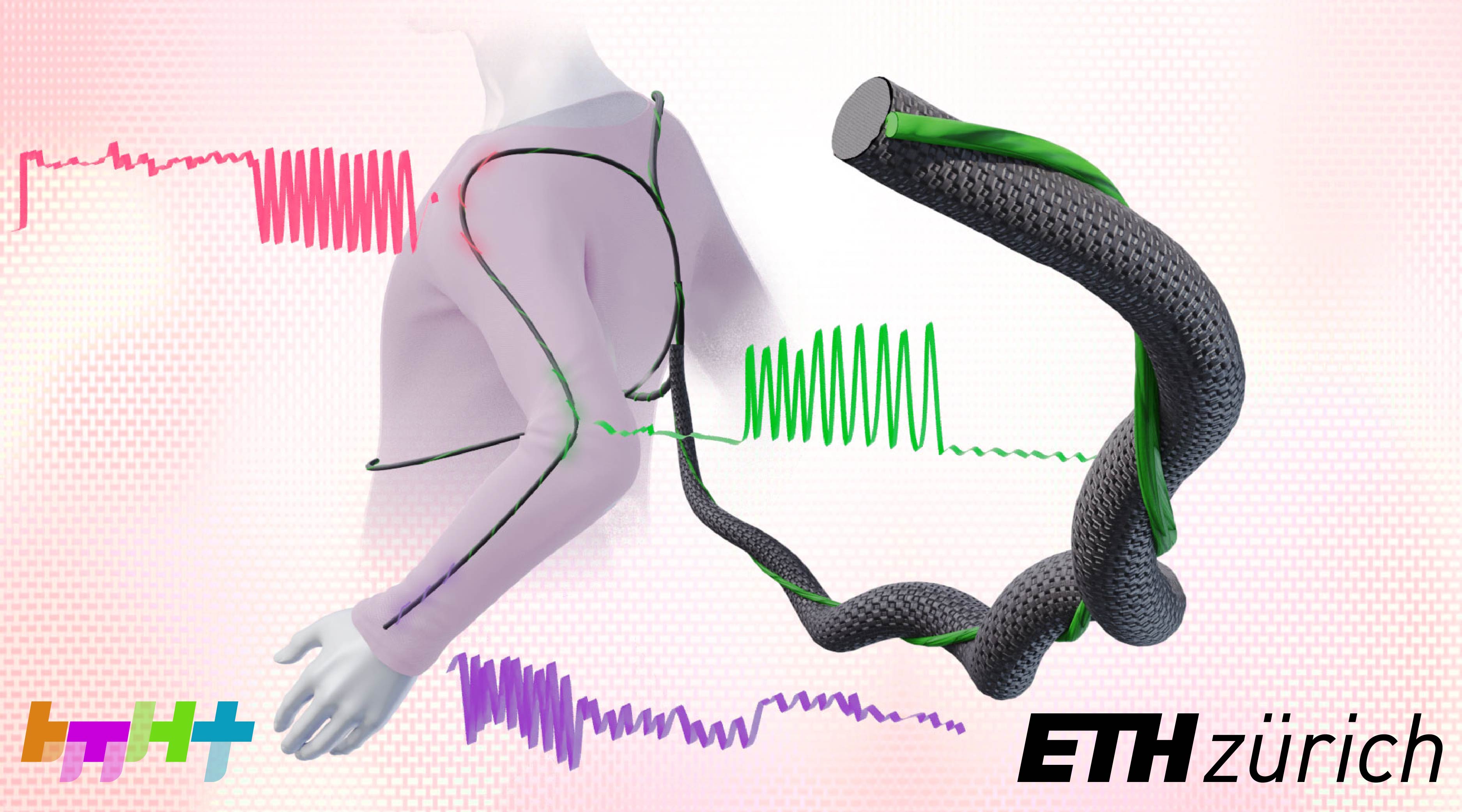
This repository includes the software, firmware, and hardware for the readout electronics used in the paper:
B. C. Hannigan, T. J. Cuthbert, C. Admadizadeh, and C. Menon, Distributed Sensing Along Fibres for Smart Clothing. April 2023. [Preprint]
The Client subfolder contains the source code for the PC client, written in Python. The client allows connection to the FPGA and optional logging of data. The data can be interpreted in a variety of formats, such as:
raw: raw ADC counts (32-bit signed integer)iq: impedances expressed as in-phase and quadrature components (equivalently, real and imagingary impedance components) in Ohms.magphase: impedances expressed as magnitude (in dB) and phase (in degrees).RCseries: impedances converted to resistance and capacitance values in an RC series circuit.RCparallel: impedances converted to resistance and capacitance values in an RC parallel circuit.model: (experimental) processed signals using a provided model (e.g., from sklearn or Keras) to convert the raw signals into a measure of interest.
Command-line arguments exist to control the COM port and logfile destination. One can also enable or disable the plotting of data to the screen and triggering ability. Note that the correct gain that matches the jumper on the PCB must be supplied via command-line argument for the scaling to be correct. There also exist some calibration curves as Excel spreadsheets.The Firmware folder contains many general-purpose logic buliding blocks such as counters, FIFOs, memories, etc. and associated test-benches. The Firmware/top subfolder contains the top-level Verilog file top.v which was used for the data collection in the paper. This relies directly on the following third-party libraries:
verilog-lfsr by Alex Forencich: https://github.com/alexforencich/verilog-lfsr. Used to implement the linear-feedback shift register that enables redundancy checking for the MIN protocol serial packets.osdvu/uart by Timothy Goddard: https://github.com/cyrozap/osdvu. Used to implement the UART.min-protocol by Ken Tindell: https://github.com/min-protocol/min. Used to frame the data sent to the PC.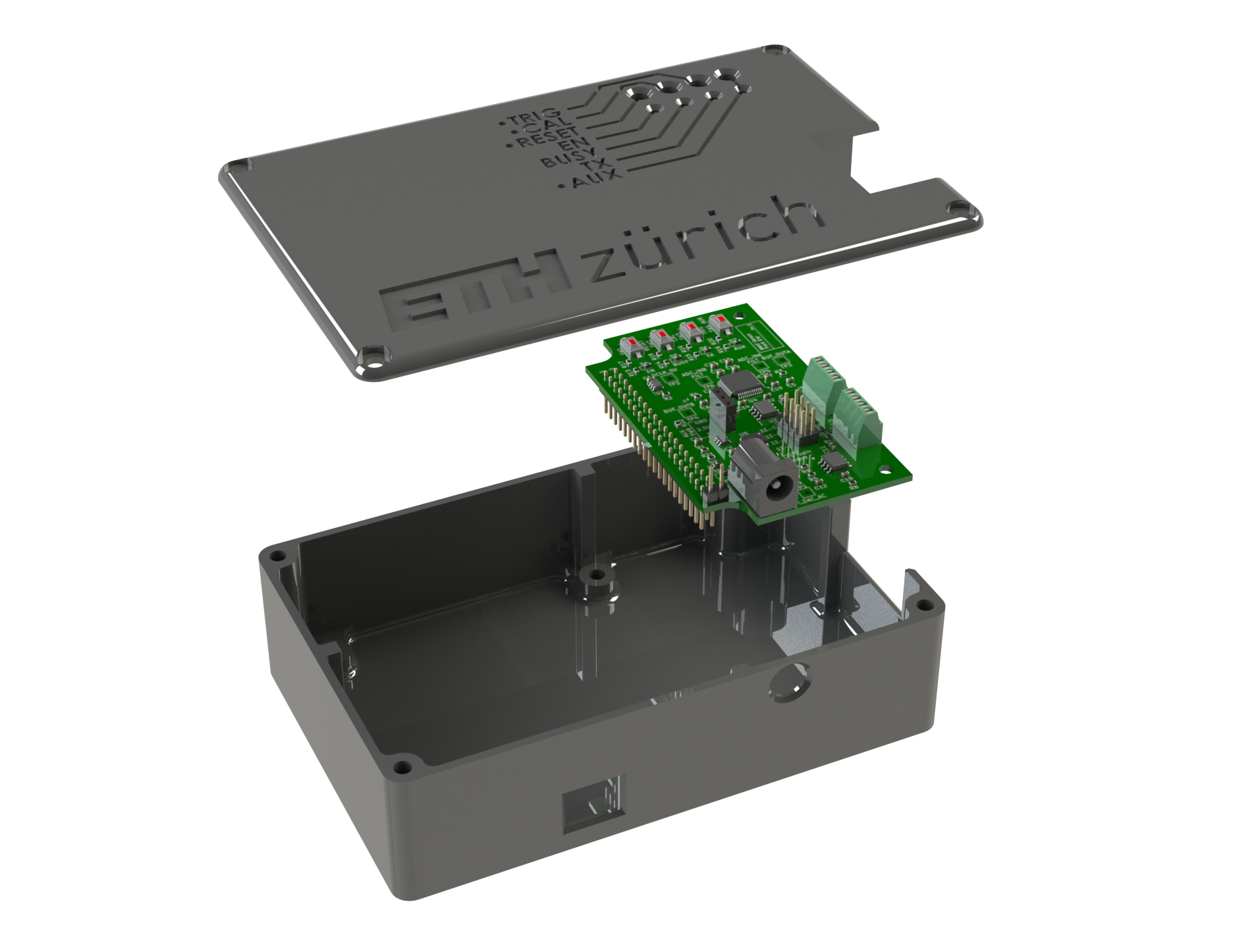
The Hardware/Enclosure subfolder contains Solidworks files for the system enclosure. These were printed on a FDM 3D printer. The Hardware/PCB subfolder contains PCB schematic and layout files from KiCAD. The other subfolders contain (disorganized) SPICE simulations, previous iterations, and other files used during development.
©2023 ETH Zurich, Brett Hannigan; D-HEST; Biomedical and Mobile Health Technology (BMHT) Lab; Carlo Menon
| Qty | Value | Footprint | References |
|---|---|---|---|
| 8 | 100n | Capacitor_SMD:C_0603_1608Metric_Pad1.08x0.95mm_HandSolder | C2, C3, C11, C12, C15, C17, C19, C23 |
| 6 | TestPoint | TestPoint:TestPoint_THTPad_2.5x2.5mm_Drill1.2mm | TP1, TP2, TP3, TP4, TP5, TP6 |
| 4 | 10u | Capacitor_SMD:C_0603_1608Metric_Pad1.08x0.95mm_HandSolder | C16, C20, C21, C24 |
| 4 | 180 | Resistor_SMD:R_0603_1608Metric_Pad0.98x0.95mm_HandSolder | R13, R14, R15, R16 |
| 4 | 4.7k | Resistor_SMD:R_0603_1608Metric_Pad0.98x0.95mm_HandSolder | R17, R18, R19, R20 |
| 3 | 10k | Resistor_SMD:R_0603_1608Metric_Pad0.98x0.95mm_HandSolder | R7, R8, R9 |
| 3 | C | Capacitor_SMD:C_0603_1608Metric_Pad1.08x0.95mm_HandSolder | C1, C9, C10 |
| 2 | 0 | Resistor_SMD:R_0603_1608Metric_Pad0.98x0.95mm_HandSolder | R21, R22 |
| 2 | 100k | Resistor_SMD:R_0603_1608Metric_Pad0.98x0.95mm_HandSolder | R5, R6 |
| 2 | 110n | Capacitor_SMD:C_0603_1608Metric_Pad1.08x0.95mm_HandSolder | C14, C22 |
| 2 | 2.2u | Capacitor_SMD:C_0603_1608Metric_Pad1.08x0.95mm_HandSolder | C4, C7 |
| 2 | 2.7n | Capacitor_SMD:C_0603_1608Metric_Pad1.08x0.95mm_HandSolder | C5, C6 |
| 2 | 20p | Capacitor_SMD:C_0603_1608Metric_Pad1.08x0.95mm_HandSolder | C13, C18 |
| 2 | 560 | Resistor_SMD:R_0603_1608Metric_Pad0.98x0.95mm_HandSolder | R3, R4 |
| 2 | Screw_Terminal_01x04 | TerminalBlock_Phoenix:TerminalBlock_Phoenix_MPT-0,5-4-2.54_1x04_P2.54mm_Horizontal | J3, J4 |
| 1 | 10 | Resistor_SMD:R_0603_1608Metric_Pad0.98x0.95mm_HandSolder | R12 |
| 1 | 100 | Resistor_SMD:R_0603_1608Metric_Pad0.98x0.95mm_HandSolder | R11 |
| 1 | 1k | Resistor_SMD:R_0603_1608Metric_Pad0.98x0.95mm_HandSolder | R10 |
| 1 | 1u | Capacitor_SMD:C_0603_1608Metric_Pad1.08x0.95mm_HandSolder | C8 |
| 1 | 22 | Resistor_SMD:R_0603_1608Metric_Pad0.98x0.95mm_HandSolder | R2 |
| 1 | 330 | Resistor_SMD:R_0603_1608Metric_Pad0.98x0.95mm_HandSolder | R1 |
| 1 | ADP7142AUJZ-R7 | ADP7142AUJZ-R7:ADP7142AUJZ-R7 | U3 |
| 1 | AUX | Diode_SMD:D_0603_1608Metric_Pad1.05x0.95mm_HandSolder | D7 |
| 1 | BLM03AX102SN1J | BLM03AX102SN1J:BEADC0603X33N | FL1 |
| 1 | BUSY | Diode_SMD:D_0603_1608Metric_Pad1.05x0.95mm_HandSolder | D5 |
| 1 | Barrel_Jack | KLDX-0202-A:KLDX-0202-A | J2 |
| 1 | Conn_01x02_Male | Connector_PinHeader_2.54mm:PinHeader_1x02_P2.54mm_Vertical | J7 |
| 1 | Conn_02x04_Odd_Even | Connector_PinHeader_2.54mm:PinHeader_2x04_P2.54mm_Vertical | J6 |
| 1 | Conn_02x20_Odd_Even | Connector_PinHeader_2.54mm:PinHeader_2x20_P2.54mm_Vertical | J1 |
| 1 | DBV0005A_N | SN74LV1T34DBVR:SN74LV1T34DBVR | U1 |
| 1 | D_Schottky | Diode_SMD:D_SOD-323_HandSoldering | D1 |
| 1 | D_Zener | Diode_SMD:D_SOD-323_HandSoldering | D2 |
| 1 | ENABLE | Diode_SMD:D_0603_1608Metric_Pad1.05x0.95mm_HandSolder | D4 |
| 1 | LM6142AIM | LM6142AIM:LM6142AIM | U2 |
| 1 | LMH6619MA_NOPB | LMH6619MA:LMH6619MA | U6 |
| 1 | LOGO | Rev2:ethz_13mm | G*** |
| 1 | PWR_ON | Diode_SMD:D_0603_1608Metric_Pad1.05x0.95mm_HandSolder | D3 |
| 1 | ST_48_ADI | AD7724ASTZ:AD7724ASTZ | U4 |
| 1 | SW_AUX | Custom:PTS636_SMTR | SW4 |
| 1 | SW_CAL | Custom:PTS636_SMTR | SW2 |
| 1 | SW_RESET | Custom:PTS636_SMTR | SW1 |
| 1 | SW_TRIG | Custom:PTS636_SMTR | SW3 |
| 1 | Screw_Terminal_01x03 | Connector_PinSocket_2.54mm:PinSocket_1x03_P2.54mm_Vertical | J5 |
| 1 | TLE2426xD | Package_SO:SOIC-8_3.9x4.9mm_P1.27mm | U5 |
| 1 | TX | Diode_SMD:D_0603_1608Metric_Pad1.05x0.95mm_HandSolder | D6 |
The 78 most common of 80 parts.
bretthannigan/sensor-readout-board
Impedance analyzer board for versatile, high-speed, and distributed sensor measurement


gregoryy01/potatoesc
This repo contains greg's attempt to make a bldc controller for Semar Urban, please be nice

louisreg/Open-TWIST
An open-source and open-hardware benchtop neurostimulator offering precise, programmable, and arbitrary waveform generation for neuroscience research.


Staacks/gbinterceptor
Capture or stream Game Boy gameplay footage via USB without modifying the Game Boy.

Chrismettal/EleLab_v2
Cheap DIY lab system for hobbyists and the tinkering folk

ohmtech-rdi/eurorack-blocks
Software to Hardware Prototyping for Eurorack using C++, Max/Gen~ or Faust

jpconstantineau/ErgoTravel
A Portable Ergonomic Split Keyboard inspired from the ErgoDox, Let's Split and Minidox
It measures 45.7 × 76.2 mm and has 2 copper layers, 1.6 mm thick.
80 parts, built around the LM6142AIM and ADP7142AUJZ-R7. The full list of its parts is on this page, with links to each part's symbol and footprint where PCBKit's library has them.
From the bretthannigan/sensor-readout-board repository on GitHub, at the commit this page was made from: the board is Hardware/PCB/SensReadPCB.kicad_pcb. PCBKit opens the board in the browser, with nothing to install.
Its repository states no licence, so its author keeps all rights: ask bretthannigan before reusing the design.