
2 layers101.6 × 88.9 mm
Automotive gateway
dexus1337/automotive-gateway
An automotive-grade, multi-protocol vehicle network interface, Man-in-the-Middle (MitM) filter, and wireless telemetry gateway
109 parts1

OpenPDM is an open-source programable Power Distribution Module for your car
OPDM is an open-source printed circuit board by brenonsantos, from the brenonsantos/OpenPDM repository on GitHub, published under the MIT licence. It is a 4-layer board of 100 × 100 mm with 156 parts on 133 nets, routed with 1,091 tracks and 305 vias.
It is built around the TJA1055T/3/1, CD74HC4067M and SP720ABG, with the SSA23L-E3 among its other parts. Its parts include 46 resistors, 41 capacitors, 17 ICs, 12 diodes and 12 transistors. It belongs with the STM32 boards of this library.


Disclaimer: This project is a work in progress! Don't blow up your stuff If you want to contribute, discuss something or chit-chat, please message me: brenonsantos96@gmail.com
OpenPDM is an open-source, programmable Power Distribution Module for car enthusiast and electronics aficionados. It is being developed by me, as my undergrad thesis. Designed to cater to the needs of electronics lovers, car enthusiasts, and tinkerers alike, OpenPDM aims to bring cheaply programmable fusebox capabilities to your project car.
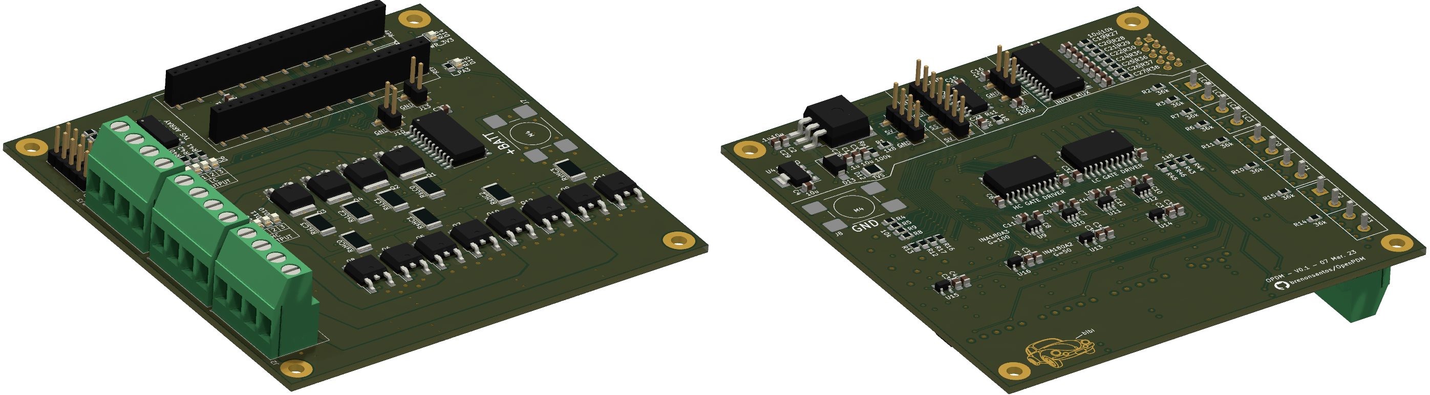
As this project is still in its early stage, contributing with work may be challenging (but I'm open to it, there is a lot to do!). Please message me first to discuss alignment and potential tasks.
More importantly, your experience, tips, or suggestions are highly welcome! If you have expertise in automotive electronics, have participated in SAE competitions, or have real-world experience, I'd love to have a conversation. My experience is watching a lot of YouTube and daily driving some old shitboxes.
Please note that OpenPDM is still in the early stages of development and has not been thoroughly tested with nominal current or in an automotive environment. Therefore, it is not even in a "ready-to-blow-up-your-car" stage.
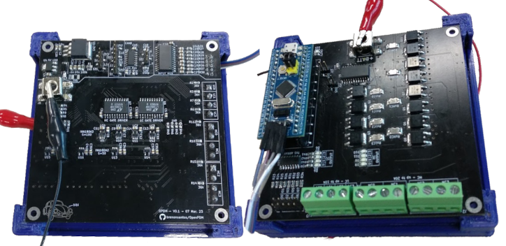
The PCB design features a 100x100mm 4-layer board using 1 Oz copper for the outer layers and 0.5 Oz copper for the inner layers (the cheapest specs from JLCPCB). Parallel layers were used to distribute the current density, allowing for a greater current capability of the thin layers used. MOSFETs were chosen instead of more advanced smart switches (like Infineon ones) to keep the project cost-effective.
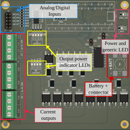
The current PCB design is a weak point in this version of the project. It was created in a week to support software development, and due to budget constraints, some cost-cutting measures were taken. As a result, there is missing redundancy and filtering components. I'll learn more about PCB design and scrap this version, and any help or expertise in this area would be greatly appreciated.
The software architecture was based on AUTOSAR because we thought it would be cool. Problem is, I didn't knew anything about AUTOSAR before starting this project, so it is kind of messy. For the next version I'll simplify the architecture and port the code to C++. The configuration of the PDM is done by modifying a single file at core/src/pdm_cfg.c. More about this.
| Qty | Value | Footprint | References |
|---|---|---|---|
| 27 | 10u | Capacitor_SMD:C_0805_2012Metric_Pad1.18x1.45mm_HandSolder | C1, C2, C3, C12, C13, C18, C19, C20, C21, C22, C23, C24, C25, C26, C27, C31 +11 |
| 16 | 10k | Resistor_SMD:R_0805_2012Metric_Pad1.20x1.40mm_HandSolder | R4, R5, R8, R9, R12, R13, R16, R17, R27, R28, R29, R30, R35, R36, R37, R38 |
| 16 | 36k | Resistor_SMD:R_0805_2012Metric_Pad1.20x1.40mm_HandSolder | R2, R3, R6, R7, R10, R11, R14, R15, R23, R24, R25, R26, R31, R32, R33, R34 |
| 12 | 100n | Capacitor_SMD:C_0805_2012Metric_Pad1.18x1.45mm_HandSolder | C9, C10, C11, C14, C15, C17, C28, C29, C36, C37, C40, C41 |
| 12 | Q_NMOS_GDS | Package_TO_SOT_SMD:TO-252-2 | Q1, Q2, Q3, Q4, Q5, Q6, Q7, Q8, Q9, Q10, Q11, Q12 |
| 11 | 1k8 | Resistor_SMD:R_0805_2012Metric_Pad1.20x1.40mm_HandSolder | R1, R18, R19, R40, R41, R42, R43, R44, R45, R46, Rs1 |
| 8 | 3m | Resistor_SMD:R_2512_6332Metric_Pad1.40x3.35mm_HandSolder | RsHC0, RsHC1, RsHC2, RsHC3, RsLC0, RsLC1, RsLC2, RsLC3 |
| 4 | INA180A2 | Package_TO_SOT_SMD:SOT-23-5_HandSoldering | U13, U14, U15, U16 |
| 4 | INA180A3 | Package_TO_SOT_SMD:SOT-23-5_HandSoldering | U9, U10, U11, U12 |
| 4 | MountingHole_Pad | MountingHole:MountingHole_3.2mm_M3_Pad | H1, H2, H3, H4 |
| 3 | Conn_01x04 | TerminalBlock_Phoenix:TerminalBlock_Phoenix_MKDS-3-4-5.08_1x04_P5.08mm_Horizontal | J1, J2, J3 |
| 2 | 150p | Capacitor_SMD:C_0805_2012Metric_Pad1.18x1.45mm_HandSolder | C16, C30 |
| 2 | 3k3 | Resistor_SMD:R_0805_2012Metric_Pad1.20x1.40mm_HandSolder | R20, R21 |
| 2 | 500 | Resistor_SMD:R_0805_2012Metric_Pad1.20x1.40mm_HandSolder | Rrth1, Rrtl1 |
| 2 | CD74HC4067M | Package_SO:SOIC-24W_7.5x15.4mm_P1.27mm | U5, U6 |
| 2 | Conn_01x01 | OPDM:Welding_Terminal_T54010B | J7, J8 |
| 2 | Conn_01x02 | Connector_PinHeader_2.54mm:PinHeader_1x02_P2.54mm_Vertical_SMD_Pin1Left | J10, J13 |
| 2 | LED_HC1 | LED_SMD:LED_0805_2012Metric_Pad1.15x1.40mm_HandSolder | D8, D9 |
| 2 | LOGO | LOGO | G***, G*** |
| 2 | LT1161CSW-PBF | Package_SO:SOIC-20W_7.5x12.8mm_P1.27mm | U7, U8 |
| 1 | 100k | Resistor_SMD:R_0805_2012Metric_Pad1.20x1.40mm_HandSolder | Rp1 |
| 1 | Conn_01x03 | Connector_PinHeader_2.54mm:PinHeader_1x03_P2.54mm_Vertical_SMD_Pin1Left | J6 |
| 1 | Conn_01x04 | Connector_PinHeader_2.54mm:PinHeader_1x04_P2.54mm_Vertical_SMD_Pin1Left | J5 |
| 1 | Conn_01x07 | Connector_PinHeader_2.54mm:PinHeader_1x07_P2.54mm_Vertical_SMD_Pin1Left | J9 |
| 1 | Conn_02x05_Odd_Even | Connector_PinHeader_2.54mm:PinHeader_2x05_P2.54mm_Vertical | J4 |
| 1 | D_TVS | Resistor_SMD:R_1210_3225Metric_Pad1.30x2.65mm_HandSolder | D12 |
| 1 | LD0186D2T50TR | Package_TO_SOT_SMD:SOT-223-3_TabPin2 | U4 |
| 1 | LD1086D2M33TR | Package_TO_SOT_SMD:TO-263-3_TabPin2 | U1 |
| 1 | LED_HC2 | LED_SMD:LED_0805_2012Metric_Pad1.15x1.40mm_HandSolder | D11 |
| 1 | LED_HC3 | LED_SMD:LED_0805_2012Metric_Pad1.15x1.40mm_HandSolder | D10 |
| 1 | LED_LC0 | LED_SMD:LED_0805_2012Metric_Pad1.15x1.40mm_HandSolder | D4 |
| 1 | LED_LC1 | LED_SMD:LED_0805_2012Metric_Pad1.15x1.40mm_HandSolder | D5 |
| 1 | LED_LC2 | LED_SMD:LED_0805_2012Metric_Pad1.15x1.40mm_HandSolder | D7 |
| 1 | LED_LC3 | LED_SMD:LED_0805_2012Metric_Pad1.15x1.40mm_HandSolder | D6 |
| 1 | LED_PWR_3V3 | LED_SMD:LED_0805_2012Metric_Pad1.15x1.40mm_HandSolder | D14 |
| 1 | LED_STATUS | LED_SMD:LED_0805_2012Metric_Pad1.15x1.40mm_HandSolder | D15 |
| 1 | SP720ABG | Package_SO:SOIC-16_3.9x9.9mm_P1.27mm | U22 |
| 1 | SSA23L | Diode_SMD:D_SMA_Handsoldering | D13 |
| 1 | STM32 BluePill | OPDM:BluePill_SMD | U3 |
| 1 | TJA1055T/3 | Package_SO:SOIC-14_3.9x8.7mm_P1.27mm | U2 |
| 1 | locked | Resistor_SMD:R_0805_2012Metric_Pad1.20x1.40mm_HandSolder | R39 |
It measures 100 × 100 mm and has 4 copper layers, 4.69 mm thick.
156 parts, built around the TJA1055T/3/1, CD74HC4067M, SP720ABG and SSA23L-E3. The full list of its parts is on this page, with links to each part's symbol and footprint where PCBKit's library has them.
From the brenonsantos/OpenPDM repository on GitHub, at the commit this page was made from: the board is Hardware/PCB_v0.1_revB/OPDM.kicad_pcb and its schematic Hardware/PCB_v0.1/OPDM.kicad_sch. PCBKit opens the board in the browser, with nothing to install.
Its repository publishes it under the MIT licence: you may reuse it on that licence's terms (keep the author's notice, and for a copyleft licence share your changes alike).
dexus1337/automotive-gateway
An automotive-grade, multi-protocol vehicle network interface, Man-in-the-Middle (MitM) filter, and wireless telemetry gateway


silveirago/MidiMood
This repository contains the code for a custom MIDI controller project called MidiMood, built using an ATmega32U4 microcontroller (or similar).

16n-faderbank/16nx
16nx is a controller for musical instruments. Sixteen faders,MIDI over USB and jack, CV out, and I2C out. Based around RP2040.


tobigun/EavesDrum
EavesDrum is an e-drum trigger module project, designed for musicians and makers. It allows you to connect drum pads or piezo triggers and converts their signals into MIDI events.

Open-Muscle/OpenMuscle-FlexGrid
60-sensor wearable with flexible PCB and pressure matrix