2 layers40 × 20 mm
 Brawn1/Speedometer
Arduino based Speed Meter for Hotweels Cars
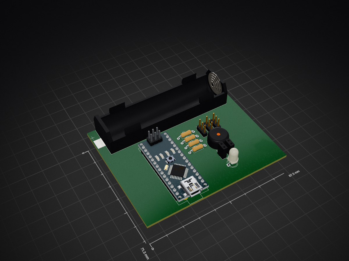
Speedometer Arduino Nano is an open-source printed circuit board by Brawn1, from the Brawn1/Speedometer repository on GitHub, published under the MIT licence. It is a 2-layer board with 13 parts on 34 nets.
Its parts include 4 resistors, 4 connectors, 1 capacitor and 1 diode. It belongs with the AVR (ATmega, ATtiny) boards of this library.
Arduino Nano basierter Geschwindigkeitsmesser fuer Hot Wheels Strecken. Zwei IR-Sensoren im Abstand von 10 cm messen die Durchfahrtszeit und ein Servomotor zeigt die Geschwindigkeit auf einer analogen Skala an.
| Komponente | Anzahl |
|---|---|
| Arduino Nano | 1 |
| IR-Sensor (digital) | 2 |
| Servomotor | 1 |
| Piezo-Lautsprecher | 1 |
| 4-fach DIP-Switch | 1 |
| LED gruen (Batterie OK) | 1 |
| LED rot (Batterie niedrig) | 1 |
| LED (Sensor 1 Status) | 1 |
| LED (Sensor 2 Status) | 1 |
| Widerstand 10k Ohm | 2 |
| 3.7V Li-Ion Akku | 1 |
| Pin | Funktion |
|---|---|
| D2 | IR-Sensor 1 (Start) |
| D3 | IR-Sensor 2 (Ziel) |
| D4 | LED gruen (Batterie OK) |
| D5 | LED rot (Batterie niedrig) |
| D6 | LED Sensor 1 |
| D7 | LED Sensor 2 |
| D8 | Piezo-Lautsprecher |
| D9 | Servomotor |
| D10 | DIP-Switch 1 (Wert 1) |
| D11 | DIP-Switch 2 (Wert 2) |
| D12 | DIP-Switch 3 (Wert 4) |
| D13 | DIP-Switch 4 (Wert 8) |
| A0 | Batteriespannung (Spannungsteiler) |
Die Batteriespannung wird ueber einen Spannungsteiler mit 2x 10k Ohm Widerstaenden gemessen. Der Spannungsteiler halbiert die Batteriespannung, damit sie im ADC-Messbereich des Arduino liegt.
Batterie+ ---[R1 10k]---+---[R2 10k]--- GND
                         |
A0Die DIP-Switches nutzen die internen Pull-Up Widerstaende des Arduino. Jeder Schalter verbindet den Pin mit GND wenn aktiv.
Pin D10-D13 ---[DIP-Switch]--- GNDDie 4 DIP-Switches steuern den Servo-Ausschlag mit 16 Stufen:
| DIP 4-3-2-1 | Wert | Multiplikator |
|---|---|---|
| 0000 | 0 | 1.0x |
| 0001 | 1 | 1.27x |
| 0010 | 2 | 1.53x |
| 0011 | 3 | 1.8x |
| 0100 | 4 | 2.07x |
| 0101 | 5 | 2.33x |
| 0110 | 6 | 2.6x |
| 0111 | 7 | 2.87x |
| 1000 | 8 | 3.13x |
| 1001 | 9 | 3.4x |
| 1010 | 10 | 3.67x |
| 1011 | 11 | 3.93x |
| 1100 | 12 | 4.2x |
| 1101 | 13 | 4.47x |
| 1110 | 14 | 4.73x |
| 1111 | 15 | 5.0x |
| Spannung | Status | LED |
|---|---|---|
| > 3.6V | OK | Gruen |
| 3.4V - 3.6V | Niedrig | Rot |
| < 3.4V | Schwach | Rot |
Die Batterie wird alle 30 Sekunden geprueft. Die Messung erfolgt mit 16-fachem Oversampling fuer stabile Werte und wird nur durchgefuehrt wenn der Servo nicht aktiv ist.
Bei Timeout (Sensor 2 nicht innerhalb von 4 Sekunden ausgeloest) wird die Messung abgebrochen.
Speedometer/
├── Code/speedometer/speedometer.ino   # Arduino Sketch
├── Kicad/                             # KiCad Schaltplan
├── Case/                              # Gehaeuse (FreeCAD)
├── LICENSE
└── README.mdSiehe LICENSE.
| Qty | Value | Footprint | References |
|---|---|---|---|
| 2 | 10k | Resistor_THT:R_Axial_DIN0207_L6.3mm_D2.5mm_P10.16mm_Horizontal | R3, R4 |
| 2 | 220 | Resistor_THT:R_Axial_DIN0207_L6.3mm_D2.5mm_P10.16mm_Horizontal | R1, R2 |
| 2 | Conn_01x02_Socket | Connector_PinSocket_2.54mm:PinSocket_1x02_P2.54mm_Vertical | J1, J3 |
| 1 | 2 Color LED Green/Red | LED_THT:LED_D5.0mm-3 | D1 |
| 1 | 440µF | Capacitor_THT:CP_Radial_D10.0mm_P5.00mm | C1 |
| 1 | Arduino_Nano_v3.x | Module:Arduino_Nano | A1 |
| 1 | Battery_Cell | Battery:BatteryHolder_Keystone_1042_1x18650 | BT1 |
| 1 | Sensor Module 1 | Connector_PinHeader_2.54mm:PinHeader_1x03_P2.54mm_Vertical | J2 |
| 1 | Sensor Module 2 | Connector_PinHeader_2.54mm:PinHeader_1x03_P2.54mm_Vertical | J5 |
| 1 | Tacho | Connector_PinHeader_2.54mm:PinHeader_1x03_P2.54mm_Vertical | M1 |
13 parts. The full list of its parts is on this page, with links to each part's symbol and footprint where PCBKit's library has them.
From the Brawn1/Speedometer repository on GitHub, at the commit this page was made from: the board is Kicad/speedometer_Arduino_Nano/speedometer_Arduino_Nano.kicad_pcb and its schematic Kicad/speedometer_Arduino_Nano/speedometer_Arduino_Nano.kicad_sch. PCBKit opens the board in the browser, with nothing to install.
Its repository publishes it under the MIT licence: you may reuse it on that licence's terms (keep the author's notice, and for a copyleft licence share your changes alike).


samyk/magspoof
A portable device that can spoof/emulate any magnetic stripe, credit card or hotel card "wirelessly", even on standard magstripe (non-NFC/RFID) readers.

fossasia/pslab-scripts
Pocket Science Lab - Scripts for Sensor Experiments


willem-pennings/balancing-cube
A cube that balances itself in a corner or edge using reaction wheels

VoronDesign/Voron-Hardware
Cool Hardware designed by the Voron Design group

hoglet67/RGBtoHDMI
Bare-metal Raspberry Pi project that provides pixel-perfect sampling of Retro Computer RGB/YUV video and conversion to HDMI