

4 layers67.3 × 48.5 mm

 bradgrantham/rocinante1
I wired up a microcontroller on a protoboard to display video on a vintage CRT TV.
Rocinante1 is an open-source printed circuit board by bradgrantham, from the bradgrantham/rocinante repository on GitHub, published under the Apache-2.0 licence. It is a 4-layer board of 150 × 101.8 mm with 143 parts on 189 nets, routed with 3,413 tracks and 363 vias.
It is built around the W9812G6KH-6 and ASE-14.31818MHZ-C-T3. Its parts include 62 resistors, 36 capacitors, 16 connectors, 5 diodes and 5 switches. It belongs with the ESP8266 and STM32 boards of this library.
I wired up a microcontroller on a protoboard to display video on a vintage CRT TV.
I call it Rocinante.
It's named after Don Quixote's horse in the novel by Miguel de Cervantes. Quixote is proud of his horse and views Rocinante as his noble steed that carries him boldy into battle. Like Don Quixote, Rocinante is actually awkward, past his prime, and engaged in a task beyond his capabilities.
I reached the limit of what I could do comfortably on a protoboard, so I designed a PCB with the peripherals I thought I might need for a beefy version of the thing. I had PCBWay make the boards and place the SMD parts. The boards arrived November 4th, 2020. I installed the through-hole parts myself.
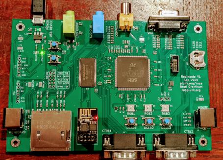
I'm keeping a spreadsheet of the status of hardware features as I bring them up.
I'm keeping rework notes for Rev1 in rework.md.
There is no framebuffer being directly scanned out in Rocinante.
Instead, there are two scanline buffers, and the CPU fills the next scanline buffer while DMA is scanning out the current scanline buffer.
Modern microcontrollers have high capabilities (the STM32H7 runs at 480MHz and has an FPU including double floats). Embedded SRAM remains expensive, however, so most of the STM32 series doesn't contain enough RAM to display e.g. double-buffered 640x480 with 8-bit pixels.
This implementation trades CPU for memory and generates video data on-the-fly (aka "racing the beam") from a handful of different video formats at the time of writing:
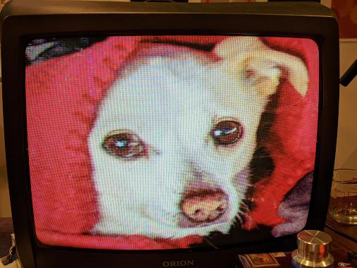 1, 2, 4, and 8-bit palettized pixmaps
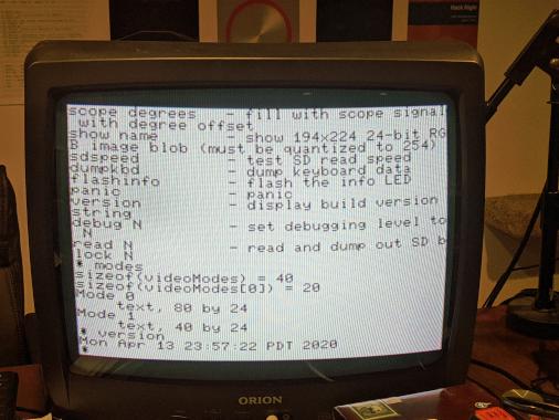
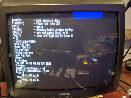 Monochrome text
The current hardware supports a composite video display using NTSC output on an 8-bit DAC. The pixel clock is 4x the color burst frequency, so typical console displays of the 1970's and 1980's should be almost directly representable. Because the data is generated one scanline ahead and some CPU capacity is left over per scanline for apps, the latency for processing can be as low as one scanline.
Applications currently include a PPM viewer, PCM audio player, rudimentary 3D model viewer, and a very limited command shell.
I originally designed this with emulation of the Apple ][, ColecoVision, and Atari 2600 in mind, but who knows if I'll ever find the time for those!
On the PCB I also laid out a bunch of pie-in-the-sky features without knowing they would work.
The protoboard version used SPI to talk to an SD card. The PCB wires an SD slot to the actual SDMMC signals on the STM32H7.
There's a 15-pin VGA header, two PS/2 jacks, and stereo audio input to give it some better media capabilities.
I daydreamed a system capable of running multiple simultaneous apps and installed 16 megabytes of SDRAM.
Over time I hope I can make most of the system function. If there's something that doesn't work but a fix is clear, maybe I'll spin a second rev of the board if I don't lose interest before then.
| Qty | Value | Footprint | References |
|---|---|---|---|
| 22 | 100nF | Capacitor_SMD:C_0603_1608Metric | C1, C2, C10, C11, C12, C13, C14, C15, C16, C17, C21, C22, C23, C24, C28, C31 +6 |
| 8 | 10K | Resistor_SMD:R_0603_1608Metric | R14, R15, R16, R21, R36, R37, R38, R39 |
| 8 | 20K | Resistor_SMD:R_0603_1608Metric | R22, R23, R43, R44, R45, R46, R47, R48 |
| 6 | 22 | Resistor_SMD:R_0603_1608Metric | R55, R56, R57, R58, R59, R60 |
| 6 | 68K | Resistor_SMD:R_0603_1608Metric | R49, R50, R51, R52, R53, R54 |
| 4 | 2.2k | Resistor_SMD:R_0603_1608Metric | R2, R20, R28, R34 |
| 3 | 10µF | Capacitor_SMD:C_0603_1608Metric | C25, C26, C27 |
| 3 | 1100 | Resistor_SMD:R_0603_1608Metric | R19, R27, R33 |
| 3 | 150 | Resistor_SMD:R_0603_1608Metric | R40, R41, R42 |
| 3 | 1µF | Capacitor_SMD:C_0603_1608Metric | C33, C35, C36 |
| 3 | 270 | Resistor_SMD:R_0603_1608Metric | R17, R25, R31 |
| 3 | 4.3k | Resistor_SMD:R_0603_1608Metric | R24, R29, R35 |
| 3 | 560 | Resistor_SMD:R_0603_1608Metric | R18, R26, R32 |
| 2 | 0 | Resistor_SMD:R_0603_1608Metric | R61, R62 |
| 2 | 2.2µF | Capacitor_SMD:C_0603_1608Metric | C3, C5 |
| 2 | 220 | Resistor_SMD:R_0603_1608Metric | R1, R4 |
| 2 | 5.1pF | Capacitor_SMD:C_0603_1608Metric | C29, C30 |
| 2 | 70nF | Capacitor_SMD:C_0603_1608Metric | C18, C19 |
| 1 | 1.7k | Resistor_SMD:R_0603_1608Metric | R8 |
| 1 | 1225 | Battery:BatteryHolder_Keystone_3001_1x12mm | BT1 |
| 1 | 14k | Resistor_SMD:R_0603_1608Metric | R11 |
| 1 | 1nF | Capacitor_SMD:C_0603_1608Metric | C20 |
| 1 | 215 | Resistor_SMD:R_0603_1608Metric | R5 |
| 1 | 25MHz | Crystal:Crystal_SMD_2016-4Pin_2.0x1.6mm | Y1 |
| 1 | 28K | Resistor_SMD:R_0603_1608Metric | R12 |
| 1 | 3.4k | Resistor_SMD:R_0603_1608Metric | R9 |
| 1 | 3V3 | TestPoint:TestPoint_Keystone_5015_Micro-Minature | TP3 |
| 1 | 4.7µF | Capacitor_SMD:C_0603_1608Metric | C34 |
| 1 | 430 | Resistor_SMD:R_0603_1608Metric | R6 |
| 1 | 47 | Resistor_SMD:R_0603_1608Metric | R13 |
| 1 | 5V | TestPoint:TestPoint_Keystone_5015_Micro-Minature | TP2 |
| 1 | 6.8k | Resistor_SMD:R_0603_1608Metric | R3 |
| 1 | 6.9k | Resistor_SMD:R_0603_1608Metric | R10 |
| 1 | 8.6k | Resistor_SMD:R_0603_1608Metric | R30 |
| 1 | 860 | Resistor_SMD:R_0603_1608Metric | R7 |
| 1 | ASE-14.31818MHz | Oscillator:Oscillator_SMD_Abracon_ASE-4Pin_3.2x2.5mm | X1 |
| 1 | AUDIOIN | Connector_Audio:Jack_3.5mm_CUI_SJ1-3535NG_Horizontal | J7 |
| 1 | AUDIOOUT | Connector_Audio:Jack_3.5mm_CUI_SJ1-3535NG_Horizontal | J8 |
| 1 | BOOT0 | Button_Switch_SMD:SW_Push_1P1T_NO_6x6mm_H9.5mm | SW5 |
| 1 | COMPOSITE | CUI_RCJ-044:CUI_RCJ-044 | J3 |
| 1 | CPST | TestPoint:TestPoint_Keystone_5015_Micro-Minature | TP1 |
| 1 | CTRL1 | Connector_Dsub:DSUB-9_Male_Horizontal_P2.77x2.84mm_EdgePinOffset7.70mm_Housed_MountingHolesOffset9.12mm | J4 |
| 1 | CTRL2 | Connector_Dsub:DSUB-9_Male_Horizontal_P2.77x2.84mm_EdgePinOffset7.70mm_Housed_MountingHolesOffset9.12mm | J5 |
| 1 | DEBUGLED | LED_SMD:LED_0603_1608Metric | D2 |
| 1 | ESP_01 | Connector_PinSocket_2.54mm:PinSocket_2x04_P2.54mm_Vertical | J1 |
| 1 | EXPHDR | Connector_PinHeader_2.54mm:PinHeader_2x05_P2.54mm_Vertical | J16 |
| 1 | F_Small | Fuse:Fuse_1210_3225Metric | F1 |
| 1 | GND | TestPoint:TestPoint_Keystone_5015_Micro-Minature | TP4 |
| 1 | HOLE0 | MountingHole:MountingHole_3.2mm_M3_Pad_Via | H1 |
| 1 | HOLE1 | MountingHole:MountingHole_3.2mm_M3_Pad_Via | H2 |
| 1 | HOLE2 | MountingHole:MountingHole_3.2mm_M3_Pad_Via | H3 |
| 1 | HOLE3 | MountingHole:MountingHole_3.2mm_M3_Pad_Via | H4 |
| 1 | I2S | Connector_PinHeader_2.54mm:PinHeader_1x06_P2.54mm_Vertical | J14 |
| 1 | KBDCLK | TestPoint:TestPoint_Keystone_5015_Micro-Minature | TP6 |
| 1 | KBDDATA | TestPoint:TestPoint_Keystone_5015_Micro-Minature | TP5 |
| 1 | KEYBOARD | Mini_din6:CUI_MD-60SM | J10 |
| 1 | LD1117S33TR_SOT223 | Package_TO_SOT_SMD:SOT-223-3_TabPin2 | U3 |
| 1 | MOUSE | Mini_din6:CUI_MD-60SM | J9 |
| 1 | NEOPIXEL | Connector_PinHeader_2.54mm:PinHeader_1x03_P2.54mm_Vertical | J15 |
| 1 | POWERLED | LED_SMD:LED_0603_1608Metric | D1 |
| 1 | Q_NPN_CBE | Package_TO_SOT_SMD:SOT-323_SC-70 | Q1 |
| 1 | RESET | Button_Switch_SMD:SW_Push_1P1T_NO_6x6mm_H9.5mm | SW1 |
| 1 | RGBLED1 | LED_SMD:LED_WS2812B_PLCC4_5.0x5.0mm_P3.2mm | D4 |
| 1 | RGBLED2 | LED_SMD:LED_WS2812B_PLCC4_5.0x5.0mm_P3.2mm | D5 |
| 1 | RGBLED3 | LED_SMD:LED_WS2812B_PLCC4_5.0x5.0mm_P3.2mm | D6 |
| 1 | SD_Card | Connector_FCI:10067847-001RLF | J12 |
| 1 | SERIAL | Connector_PinHeader_2.54mm:PinHeader_1x06_P2.54mm_Vertical | J11 |
| 1 | STM32H743IITx | Package_QFP:LQFP-176_24x24mm_P0.5mm | U1 |
| 1 | SWD | Connector_PinHeader_1.27mm:PinHeader_2x05_P1.27mm_Vertical_SMD | J2 |
| 1 | USBFS/POWER | Connector_USB:USB_Micro-B_Amphenol_10104110_Horizontal | J13 |
| 1 | USER1 | Button_Switch_SMD:SW_Push_1P1T_NO_6x6mm_H9.5mm | SW2 |
| 1 | USER2 | Button_Switch_SMD:SW_Push_1P1T_NO_6x6mm_H9.5mm | SW3 |
| 1 | USER3 | Button_Switch_SMD:SW_Push_1P1T_NO_6x6mm_H9.5mm | SW4 |
| 1 | VGA | DSUB15HD:HD15-SN-24 | J6 |
| 1 | W9812G6KH-6 | Package_SO:TSOP-II-54_22.2x10.16mm_P0.8mm | U2 |
The 142 most common of 143 parts.


LIV2/RIDE
To add the A0 Bonus RAM to the system you will need to use the addram command included in the RIDE-Software adf/lha found under Releases.


harrislab-brown/CyberDiver
Untethered cyber-physical robotic platform for water entry experiments

It measures 150 × 101.8 mm and has 4 copper layers, 1.6 mm thick.
143 parts, built around the W9812G6KH-6 and ASE-14.31818MHZ-C-T3. The full list of its parts is on this page, with links to each part's symbol and footprint where PCBKit's library has them.
From the bradgrantham/rocinante repository on GitHub, at the commit this page was made from: the board is kicad/rocinante1/rocinante1.kicad_pcb. PCBKit opens the board in the browser, with nothing to install.
Its repository publishes it under the Apache-2.0 licence: you may reuse it on that licence's terms (keep the author's notice, and for a copyleft licence share your changes alike).