4 layers109.1 × 91.2 mm
 bquangDinh/telemetry-node
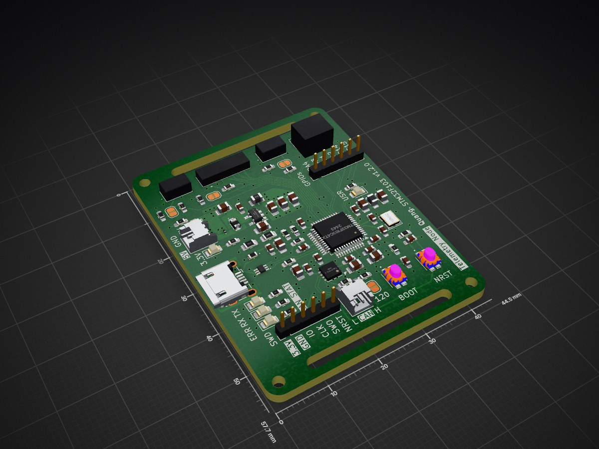
Telemetry node is an open-source printed circuit board by bquangDinh, from the bquangDinh/telemetry-node repository on GitHub. It is a 4-layer board of 44.5 × 57.7 mm with 84 parts on 65 nets, routed with 606 tracks and 141 vias.
It is built around the TLV62569DBVR-TP, TJA1051TK/3/1 and USBLC6-2P6, with the SKTHAHE010, CUHS20S30,H3F and ESDA7P60-1U1M among its other parts. Its parts include 25 capacitors, 23 resistors, 9 diodes, 9 connectors and 4 ICs. It belongs with the STM32 boards of this library.


| Qty | Value | Footprint | References |
|---|---|---|---|
| 11 | 100n | Capacitor_SMD:C_0603_1608Metric_Pad1.08x0.95mm_HandSolder | C1, C5, C6, C11, C13, C14, C15, C17, C19, C21, C58 |
| 5 | 10u | Capacitor_SMD:C_0805_2012Metric_Pad1.18x1.45mm_HandSolder | C16, C20, C23, C24, C59 |
| 5 | 1u | Capacitor_SMD:C_0805_2012Metric_Pad1.18x1.45mm_HandSolder | C2, C7, C9, C10, C25 |
| 5 | 470 | Resistor_SMD:R_0603_1608Metric_Pad0.98x0.95mm_HandSolder | R8, R29, R32, R33, R34 |
| 4 | MountingHole | MountingHole:MountingHole_2.2mm_M2 | H1, H2, H3, H4 |
| 4 | SolderJumper_2_Open | Jumper:SolderJumper-2_P1.3mm_Open_RoundedPad1.0x1.5mm | JP1, JP2, JP3, JP4 |
| 3 | 10k | Resistor_SMD:R_0603_1608Metric_Pad0.98x0.95mm_HandSolder | R1, R11, R12 |
| 2 | 120 | Resistor_SMD:R_0603_1608Metric_Pad0.98x0.95mm_HandSolder | R13, R30 |
| 2 | 14p | Capacitor_SMD:C_0603_1608Metric_Pad1.08x0.95mm_HandSolder | C12, C18 |
| 2 | 33 | Resistor_SMD:R_0603_1608Metric_Pad0.98x0.95mm_HandSolder | R7, R18 |
| 2 | 4k7 | Resistor_SMD:R_0603_1608Metric_Pad0.98x0.95mm_HandSolder | R15, R16 |
| 2 | 5.1k | Resistor_SMD:R_0603_1608Metric_Pad0.98x0.95mm_HandSolder | R4, R5 |
| 2 | 53048-0210 | SamacSys_Parts:SHDRRA2W35P0X125_1X2_425X550X350P | J3, J4 |
| 2 | LED | LED_SMD:LED_0805_2012Metric_Pad1.15x1.40mm_HandSolder | D11, D12 |
| 2 | SKTHAHE010 | SamacSys_Parts:SKTHAHE010 | S3, S4 |
| 2 | Undecided | Resistor_SMD:R_0603_1608Metric_Pad0.98x0.95mm_HandSolder | R2, R17 |
| 1 | 100k | Resistor_SMD:R_0805_2012Metric_Pad1.20x1.40mm_HandSolder | R14 |
| 1 | 10n | Capacitor_SMD:C_0603_1608Metric_Pad1.08x0.95mm_HandSolder | C8 |
| 1 | 120R | Inductor_SMD:L_0805_2012Metric_Pad1.05x1.20mm_HandSolder | FB1 |
| 1 | 16MHz | Crystal:Crystal_SMD_3225-4Pin_3.2x2.5mm | Y1 |
| 1 | 1k5 | Resistor_SMD:R_0603_1608Metric_Pad0.98x0.95mm_HandSolder | R3 |
| 1 | 2.2u | SamacSys_Parts:LQM2HPZ3R3MJ0B | L2 |
| 1 | 33k | Resistor_SMD:R_0603_1608Metric_Pad0.98x0.95mm_HandSolder | R6 |
| 1 | 450k | Resistor_SMD:R_0805_2012Metric_Pad1.20x1.40mm_HandSolder | R10 |
| 1 | 53047-0410 | SamacSys_Parts:530470410 | J5 |
| 1 | 53047-0710 | SamacSys_Parts:530470710 | J1 |
| 1 | 6.8p | Capacitor_SMD:C_0805_2012Metric_Pad1.18x1.45mm_HandSolder | C22 |
| 1 | 82k | Resistor_SMD:R_0603_1608Metric_Pad0.98x0.95mm_HandSolder | R9 |
| 1 | CAN_ERR | LED_SMD:LED_0805_2012Metric_Pad1.15x1.40mm_HandSolder | D15 |
| 1 | CUHS20S30,H3F | SamacSys_Parts:CUHS20S40H3F | D3 |
| 1 | Conn_01x06_Pin | Connector_PinHeader_2.00mm:PinHeader_1x06_P2.00mm_Vertical | J6 |
| 1 | ESDA7P60-1U1M | SamacSys_Parts:ESDA7P601U1M | D2 |
| 1 | Fuse | Fuse:Fuse_0603_1608Metric_Pad1.05x0.95mm_HandSolder | F2 |
| 1 | PESD5V0X1BCSFYL | SamacSys_Parts:PMEG3005AESFYL | D1 |
| 1 | RX | LED_SMD:LED_0805_2012Metric_Pad1.15x1.40mm_HandSolder | D7 |
| 1 | S1 | SamacSys_Parts:530470310 | J14 |
| 1 | S2 | SamacSys_Parts:530470310 | J15 |
| 1 | STM32F103C4Tx | Package_QFP:LQFP-48_7x7mm_P0.5mm | U1 |
| 1 | SWD | Connector_PinHeader_2.00mm:PinHeader_1x06_P2.00mm_Vertical | J2 |
| 1 | TJA1051TK-3 | Package_DFN_QFN:DFN-8-1EP_3x3mm_P0.65mm_EP1.55x2.4mm | U2 |
| 1 | TLV62569DBVR | SamacSys_Parts:SOT95P280X145-5N | IC1 |
| 1 | TX | LED_SMD:LED_0805_2012Metric_Pad1.15x1.40mm_HandSolder | D6 |
| 1 | USBLC6-2P6 | SamacSys_Parts:USBLC62P6 | IC2 |
| 1 | USB_B_Micro | Connector_USB:USB_Micro-B_Wuerth_629105150521 | J11 |
| 1 | USER LED 1 | LED_SMD:LED_0805_2012Metric_Pad1.15x1.40mm_HandSolder | D16 |
It measures 44.5 × 57.7 mm and has 4 copper layers, 2.22 mm thick.
84 parts, built around the TLV62569DBVR-TP, TJA1051TK/3/1, USBLC6-2P6 and SKTHAHE010. The full list of its parts is on this page, with links to each part's symbol and footprint where PCBKit's library has them.
From the bquangDinh/telemetry-node repository on GitHub, at the commit this page was made from: the board is telemetry-node.kicad_pcb and its schematic power.kicad_sch. PCBKit opens the board in the browser, with nothing to install.
Its repository states no licence, so its author keeps all rights: ask bquangDinh before reusing the design.


Stan-debakker/grap-6TWEA
Daarnaast moest ik ervoor zorgen dat de nieuwe sensoren correct werken. Ik ben gestart met experimenteren via Arduino IDE, zie "codearduinoIDE".

takuhoTech/LagopusSystem-2023
Avionics for Human-Powered Aircraft, Including Bike Power Meter project.


ElektorLabs/lorawan-sensor-node-v2
Solar Powered LoRaWAN Sensor Node V2

hoffmatic/SD-2-EKF
This folder contains the live KiCad project files and local component libraries:

ParadigmEngineering/aks-2026-hardware
Autonomous Karting Series (2026) hardware for Paradigm Engineering