
2 layers27.9 × 16.5 mm

a Printed Circuit Board to extend the M-Bus of M5stack for probing and testing M-Bus modules.
Bf-033 is an open-source printed circuit board by botanicfields, from the botanicfields/PCB-MBUS-Extension repository on GitHub, published under the CC0-1.0 licence. It is a 2-layer board of 78.4 × 100 mm with 18 parts on 26 nets, routed with 346 tracks and 36 vias.
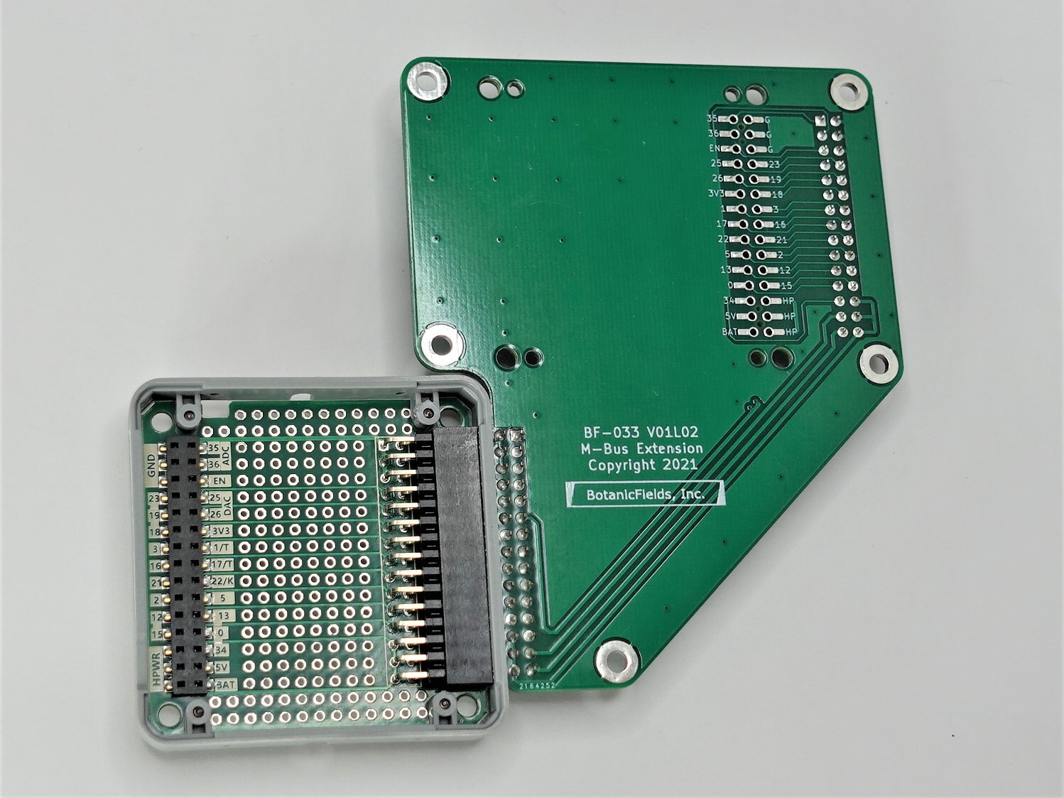
a Printed Circuit Board of M-Bus Extension for M5Stack
M5Stackの外にM-Busモジュールを接続するエクステンション基板のキットです。M5Stack用BUSモジュールに取り付けて使用します。
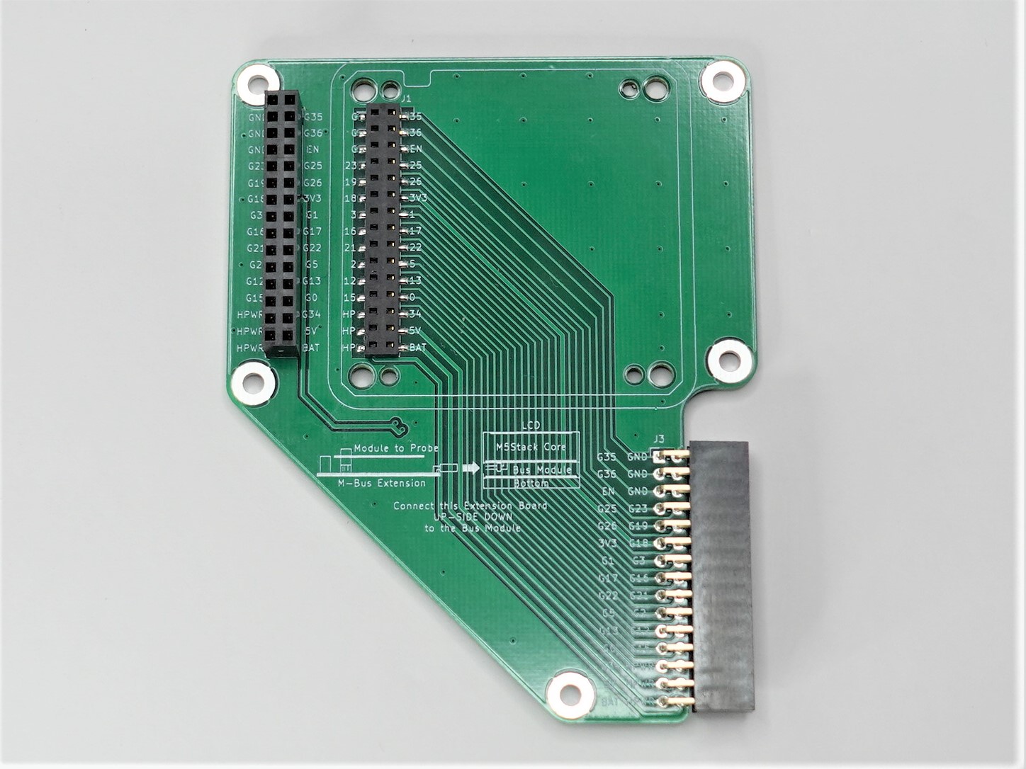
https://www.switch-science.com/catalog/7371/
※ M5Stack用BUSモジュールは付属しません。別途ご用意ください。
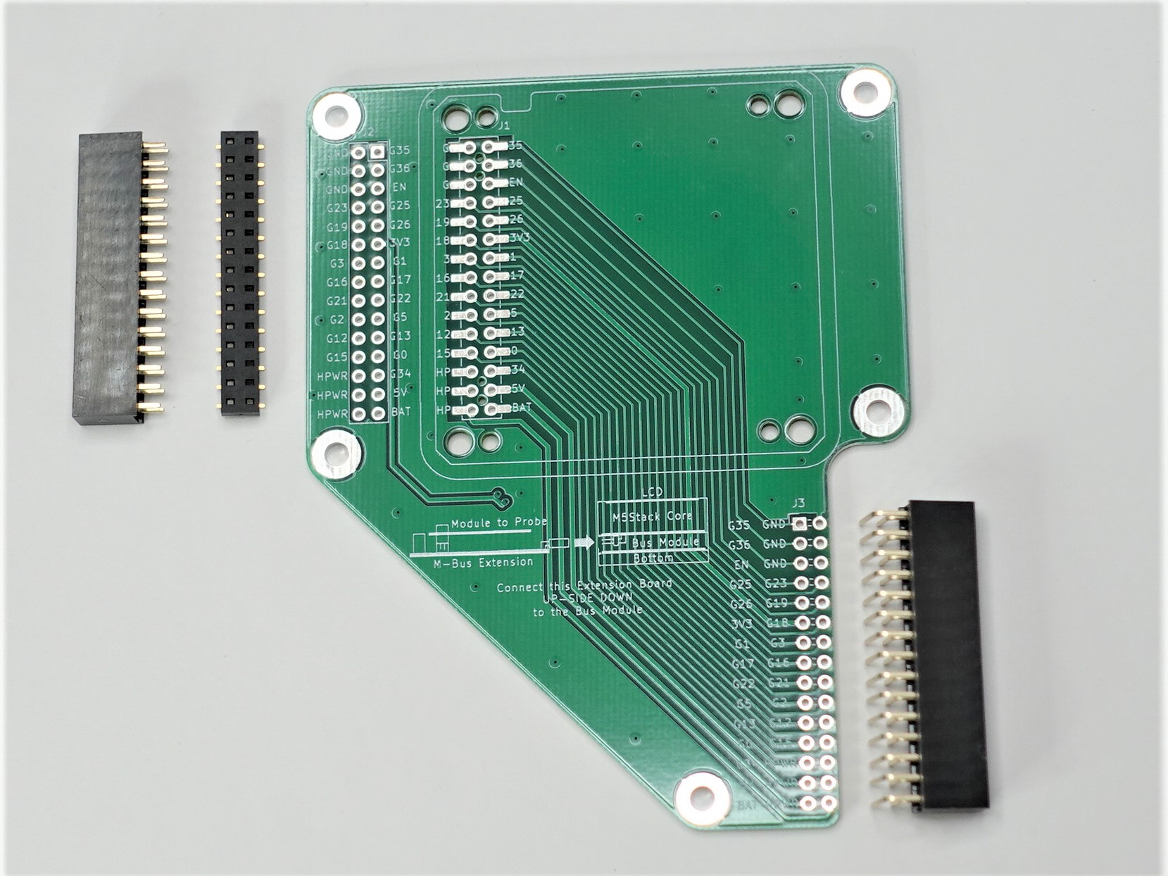
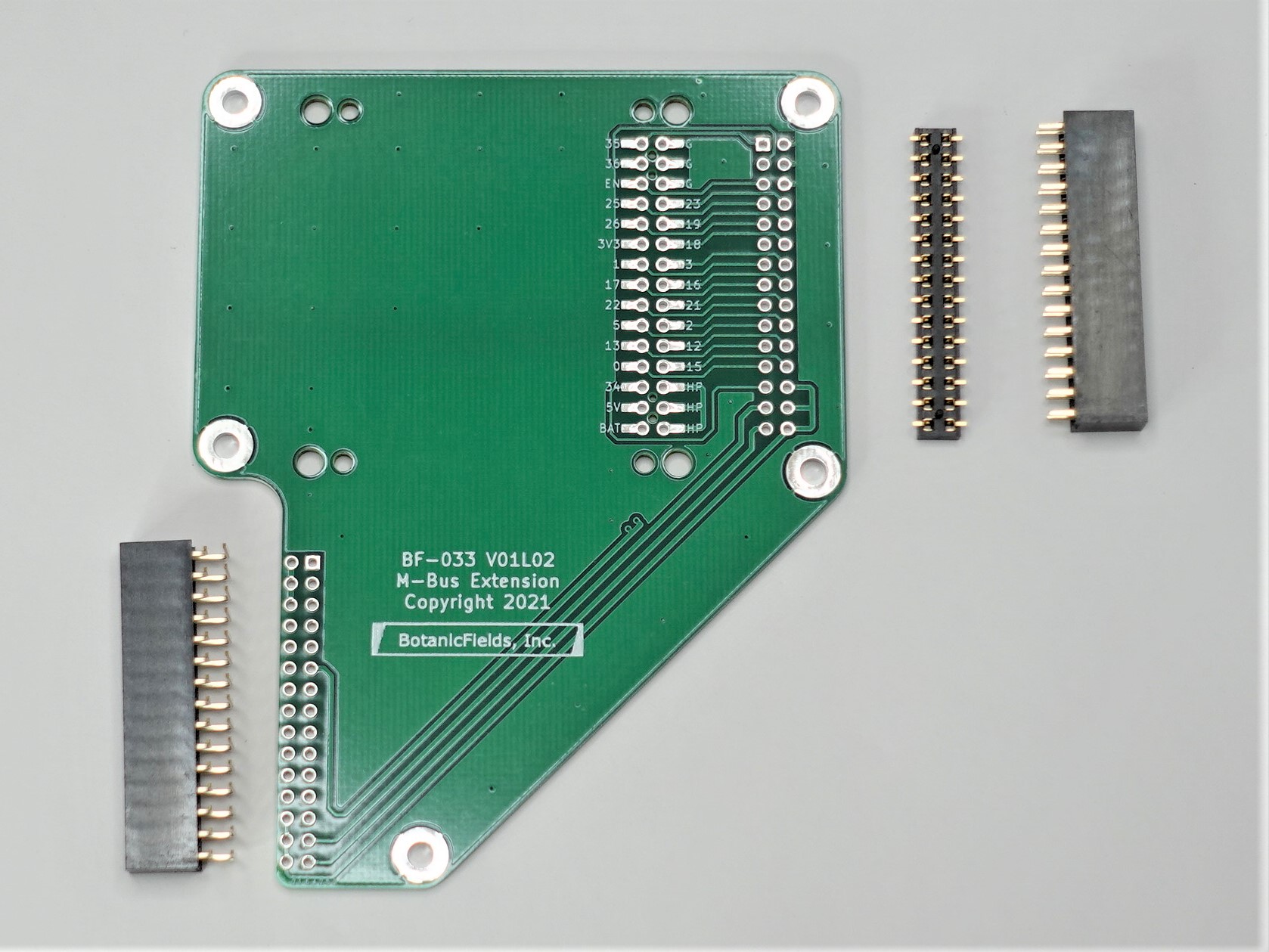
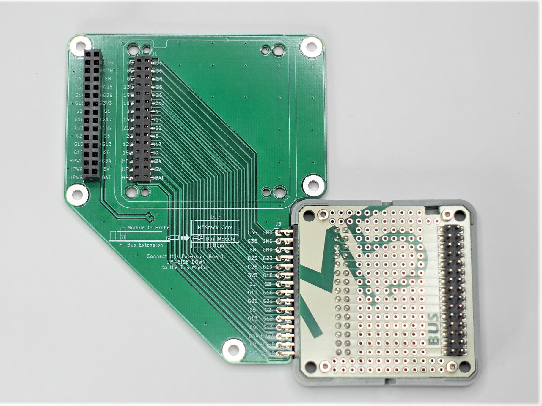
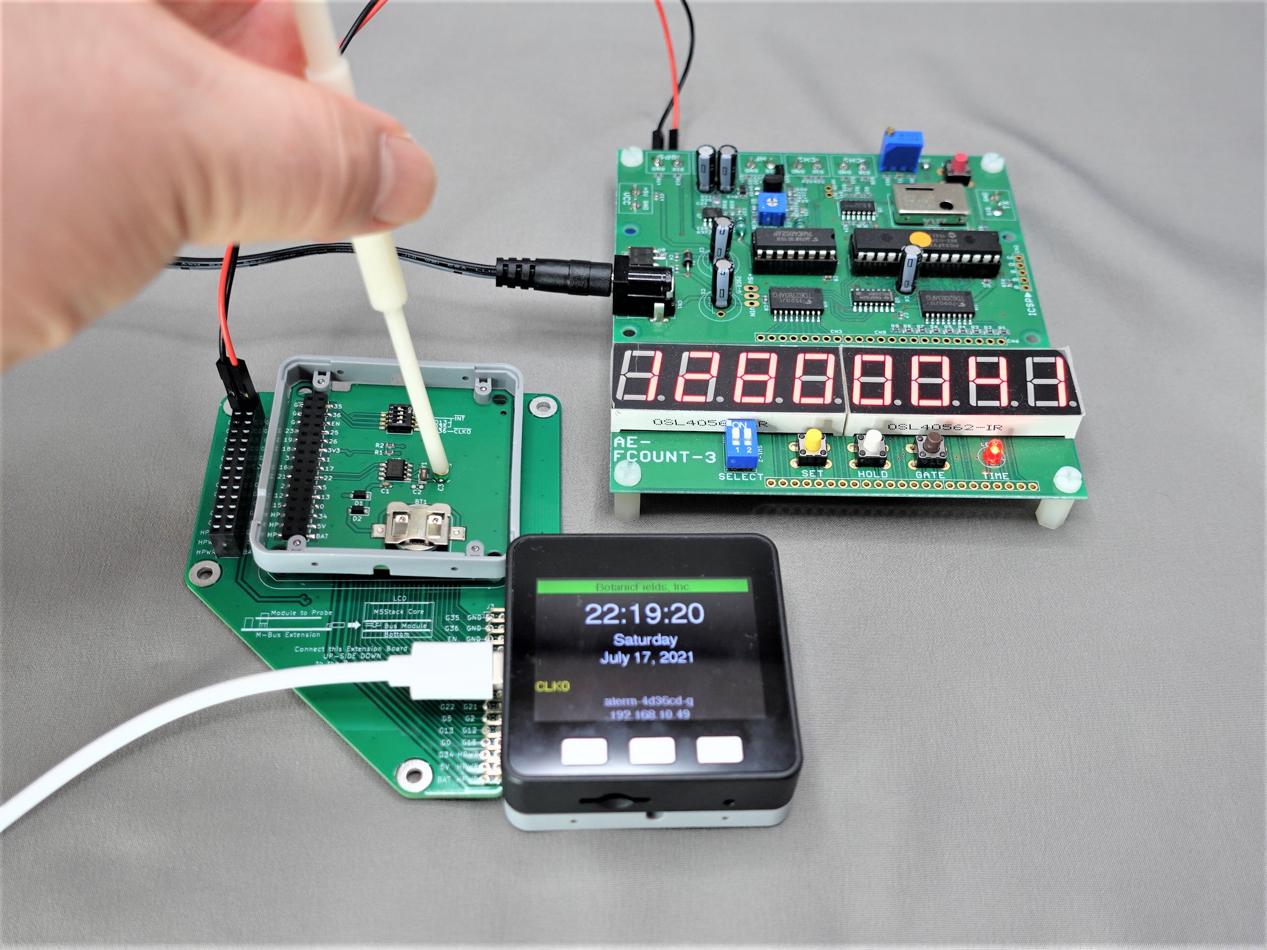
RTCモジュールのCLKO信号を、M-Busエクステンション基板のGPIO36から取り出して周波数カウンタで観測しながら、RTCモジュールの水晶発振子のトリマを調整しています。M5StackのLCDも同時に見ることができます。
| Qty | Value | Footprint | References |
|---|---|---|---|
| 4 | MountingHole | bf:BF@MountingHole_2.2mm_M2 | H5, H6, H7, H8 |
| 4 | MountingHole | bf:BF@MountingHole_3.2mm_M3 | H1, H2, H3, H4 |
| 1 | |||
| 1 | LOGO | bf:BF@logo4 | G*** |
| 1 | M-BUS | bf:BF@M5Stack_MBUS | J1 |
| 1 | M-BUS | Connector_PinHeader_2.54mm:PinHeader_2x15_P2.54mm_Horizontal | J3 |
| 1 | M-BUS | Connector_PinSocket_2.54mm:PinSocket_2x15_P2.54mm_Vertical | J2 |
The 13 most common of 18 parts.
It measures 78.4 × 100 mm and has 2 copper layers, 1.6 mm thick.
18 parts. The full list of its parts is on this page, with links to each part's symbol and footprint where PCBKit's library has them.
From the botanicfields/PCB-MBUS-Extension repository on GitHub, at the commit this page was made from: the board is V01L02/KiCad/bf-033/bf-033.kicad_pcb. PCBKit opens the board in the browser, with nothing to install.
Its repository publishes it under the CC0-1.0 licence: you may reuse it on that licence's terms (keep the author's notice, and for a copyleft licence share your changes alike).

VoronDesign/Voron-Hardware
Cool Hardware designed by the Voron Design group


hackclub/OnBoard
💡 Join 1,000 teenagers and make your first PCB with a $100 grant!

VoronDesign/Voron-Tap
Tap is a nozzle-based z-probe for the V2 and Trident printer designs. The entire toolhead moves to trigger an optical switch. Tap offers many advantages:

Luos-io/luos_engine
Open-source and real-time orchestrator for cyber-physical-systems, to easily design, test and deploy embedded applications and digital twins.


Twotoz/C5VRX
Ultra-minimal, zero-CPU 5.8 GHz analog FPV video receiver using ESP32-C5 Wi-Fi 6 PHY MODEM_DIAG, BitScrambler WBFM demodulation & resistor DAC CVBS