2 layers43 × 23 mm

 bocaj88/gpsspeed
Open-source GPS replacement for the PerfectPass paddlewheel speed sensor (ESP32-C3 + GPS board, firmware, research). Built for a 2008 MasterCraft X2.
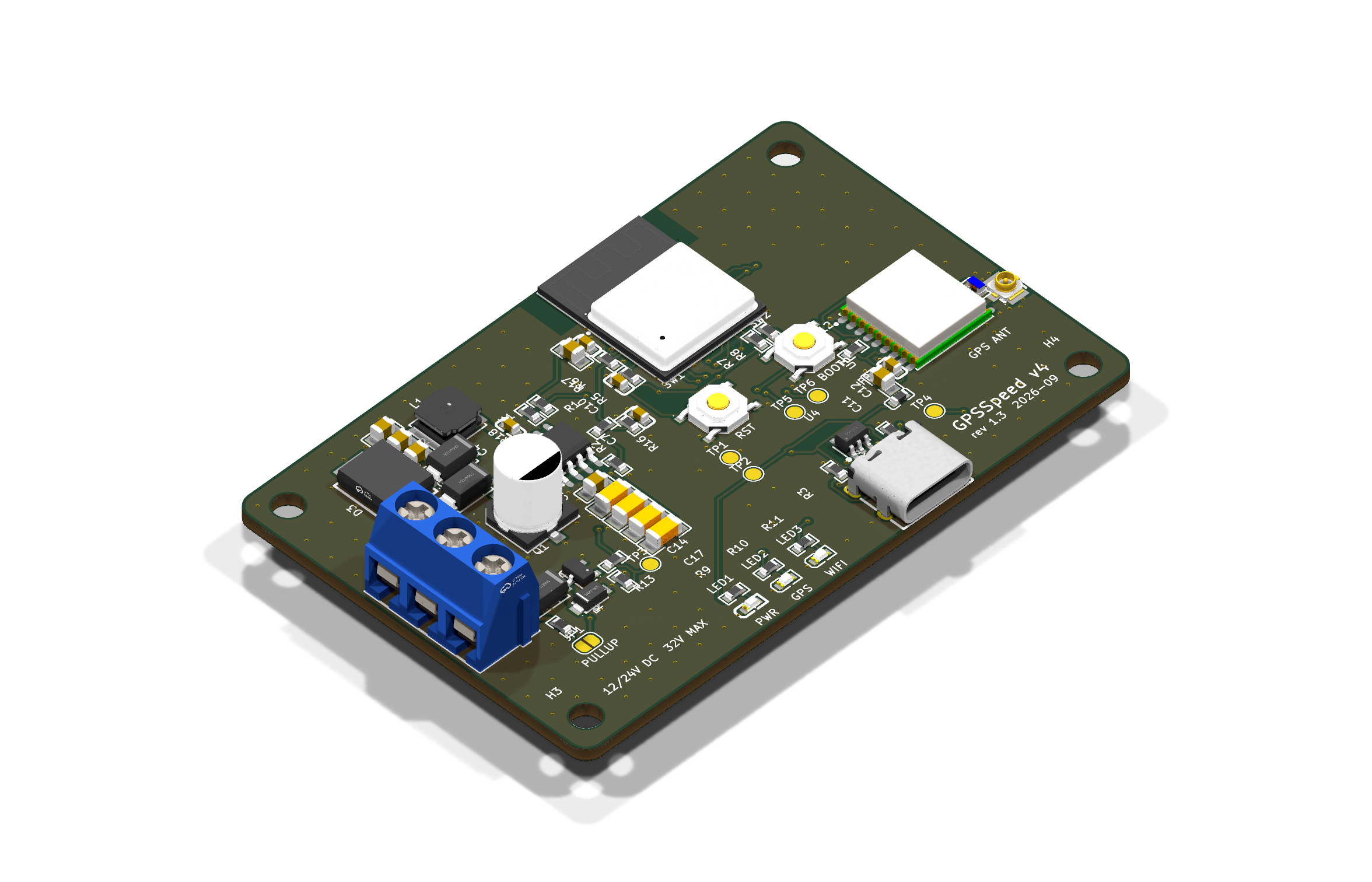
Gpsspeed is an open-source printed circuit board by bocaj88, from the bocaj88/gpsspeed repository on GitHub, published under the MIT licence. It is a 2-layer board of 72 × 46 mm with 67 parts on 39 nets, routed with 506 tracks and 244 vias.
It is built around the ATGM336H-5N31, ESP32-C3-MINI-1-H4 and USBLC6-2SC6. Its parts include 18 resistors, 16 capacitors, 8 diodes, 4 ICs and 3 connectors. It belongs with the radio and wireless boards and the ESP32 and RISC-V boards of this library.


GPS → paddlewheel pulse emulator for PerfectPass, rebuilt as a JLCPCB-assembled board. Replaces the Uno + perfboard hat.
| Size | 72 × 46 mm, 2 layers, 1.6 mm, 4× M3 holes |
| Power | 12/24 V DC nominal, 32 V continuous max. 60 V polyfuse → 1.5 kW bidirectional TVS (±58 V clamp) → 100 V reverse-polarity Schottky → 22 µF/100 V bulk + 4 × 2.2 µF/100 V → LMR38010 buck (80 V operating, 85 V abs max). USB-C on the bench. |
| Brain | ESP32-C3-MINI-1-H4 (WiFi boot window, OTA updates; 105 °C part) |
| GPS | ATGM336H-5N31 (GPS+BeiDou, 10 Hz), u.FL for the existing active antenna |
| Output | ZXMS6004FF self-protected low-side switch (60 V, current limit, thermal shutdown, active clamp) behind a series Schottky (swapped +12 V/GND can't back-drive the dash), 33 V TVS on the drain; survives SIGNAL wired to +12 V; optional pull-up to the input rail via JP1 (ships open) |
| Connector | J1 screw terminal: 1 = +12 V, 2 = GND, 3 = SIGNAL (wires enter from the board edge) |
| LEDs | PWR (red), GPS (green), WIFI (green) |
| Review item | Change |
|---|---|
| Stop-ship: SIGNAL wired to +12 V shorts the supply through D5 and a bare 2N7002K the first time Q1 turns on | Q1 → ZXMS6004FF IntelliFET: current limit 0.7–1.7 A, thermal shutdown with auto-restart, short-circuit protected to VDS 36 V. Specified for 3.3 V logic (VIH 3 V, 0.6 Ω max at 3 V) |
| D4 (53 V max clamp) vs Q1 (60 V) margin thin | Q1's own active clamp is 60–70 V / 90 mJ, so a spike past D4 is absorbed by design instead of avalanching a bare MOSFET |
| (follows from the above) | SIGNAL_OUT / SIGNAL_DRAIN routed at 0.5 mm for the 1.7 A fault current |
Bench items from that review (not schematic errors): output-low level with D5 in series against the real PerfectPass input; USB-only startup at ~4.6 V into the buck. JP1 stays open on 24 V boats. Q1 switching: ~15 µs on / ~60 µs off. Constant edge delays leave the output frequency unchanged; duty shifts by ~1 % at 60 MPH.
| Review item | Change |
|---|---|
| C16 only 63 V against a 58 V clamp | 22 µF / 100 V, same series and 6.3 × 7.7 can (RV100V22M6X8) |
| Battery-sense pin reaches 3.6 V at the clamp | R1 150k → 220k (×23): 32 V reads 1.4 V, the 58 V clamp 2.5 V. Firmware 4.0.2 |
| Input ceramics borderline after DC-bias derating | 4th 2.2 µF / 100 V (C17) |
| 24 V pull-up would forward-bias D5 and make D4 clamp continuously | Q1 → 2N7002K 60 V, D4 → SMF33A (33 V standoff, 53 V clamp < 60 V) |
| Buck exposed pad: one full paste opening, no thermal path | Paste split into 4 windows (60 %); 2 tented GND vias just past the GND-pin end of the pad; pad tied solid into the pour |
| (found while re-checking) | Two u.FL stitching vias overlapped fanout vias (drill-to-drill). Fanout now avoids existing vias, and drill spacing fails the build |
Not changed: L1 stays where it is (SW node ~8.7 mm total; moving it means relocating D2 in the packed input corner — the reviewer rated it optional for prototypes). D2 stays an SS310: it has to block up to ~53 V when USB and boat power are both connected, and USB power is bench-only.
| Review item | Change |
|---|---|
| "12–24 V" label wrong (old TVS conducted ~20 V) | Input re-rated; silk now reads 12/24V DC 32V MAX |
| TVS + PTC too close to the AP63203's 35 V abs max | Buck → LMR38010 (80 V / 85 V abs), TVS → SMCJ36CA 1.5 kW bidirectional, PTC → 60 V, D1/D2 → SS310 100 V, input ceramics → 100 V, + 47 µF/63 V bulk |
| L2's 1.2 GHz SRF below GPS L1 | L2 → Murata LQW18AN27NG wirewound, SRF 3.7 GHz |
| SIGNAL back-drive on reverse wiring | D5 SS310 in series at J1 pin 3 (chosen over a resistor so a stiff head-unit pull-up can't break the low level; adds ~0.3 V) |
| Open via-in-pad under the ESP32 | Removed; also stripped 4 open vias JLC's footprint put in the buck's exposed pad |
| Buck loop / u.FL grounding | Hand-routed C3–VIN–GND loop (~2 mm), SW straight into L1, FB on the quiet side; 8 stitching vias around the u.FL |
Not changed (reviewed and accepted): USB diode-OR (verify startup during WiFi TX on the bench), reboot on very deep crank dips (firmware ignores brownouts for rollback), SMF15A on the drain (24.4 V clamp < Q1's 30 V).
Potting: keep resin off the ESP32 antenna end (top edge) — resin detunes the PCB antenna. Leave an air pocket there, or pot only the lower two-thirds of the board.
pcb/
  gpsspeed.kicad_pro / .kicad_sch / .kicad_pcb   open in KiCad 10
  gpsspeed.kicad_dru      two scoped DRC exceptions (explained inside)
  lib/                    exact JLC footprints/symbols/3D (easyeda2kicad)
  gen/                    the generators -- design.py is the netlist source of truth
  out/jlcpcb/             gerbers.zip, bom_jlcpcb.csv, cpl_jlcpcb.csv   <- upload these
  out/                    schematic PDF, assembly PDF, STEP, renders
firmware/gpsspeed_v4/     ESP32-C3 firmware; bin/ has prebuilt images
firmware/test/ host-side tests of the pulse + calibration codeout/jlcpcb/gerbers.zip. Defaults are right: 2 layers, 1.6 mm,
HASL lead-free, green. Qty 5 (the minimum).bom_jlcpcb.csv and cpl_jlcpcb.csv.Rev 1.1 quote (2026-09-26), for reference: 5 assembled boards $162.84, + UPS ~$37 + US customs duty ~$61 (JLC collects it up front with DDP shipping) − $10 coupon ≈ $251.
esptool.py --chip esp32c3 write_flash 0x0 firmware/gpsspeed_v4/bin/gpsspeed_v4-4.0.8-usb-full.binarduino-cli upload — build command is in gpsspeed_v4.ino). If it won't
connect, hold BOOT, tap RST, release BOOT.chars: climbing and ant:OK once the antenna
is on. ant:OPEN = antenna not connected / passive; ant:SHORT = cable fault.GPSSpeed-XXXX (open, no password; XXXX is fixed per board) → the page pops up, tap Done → later just open http://gpsspeed.local
(Safari; a captive-portal sheet may open on its own).-ota.bin. A bad build that
crash-loops rolls back to the previous one automatically; brownouts from engine
cranking do not count as crashes.$PCAS01/02/03) follow ZhongKe's documented format. If
the module ignores one, the firmware still works at its defaults (9600 baud, 1 Hz)
— the web UI shows the actual baud/rate it achieved.cd pcb/gen
~/Applications/KiCad/KiCad.app/Contents/Frameworks/Python.framework/Versions/3.9/bin/python3 gen_sch.py
~/Applications/KiCad/KiCad.app/Contents/Frameworks/Python.framework/Versions/3.9/bin/python3 build.py # place, route, pour, DRC
python3 gen_outputs.py # JLC filesbuild.py needs Freerouting (~/Applications/freerouting) and Java ≥ 25
(brew install openjdk). Edit design.py for circuit changes, gen_pcb.py for
placement.
| Qty | Value | Footprint | References |
|---|---|---|---|
| 6 | 10k | gpsspeed:R0603 | R2, R5, R6, R7, R8, R12 |
| 4 | 100nF | gpsspeed:C0603 | C4, C7, C9, C12 |
| 4 | 2.2uF 100V | gpsspeed:C1206 | C1, C2, C14, C17 |
| 4 | M3 | MountingHole:MountingHole_3.2mm_M3 | H1, H2, H3, H4 |
| 3 | 100R | gpsspeed:R0603 | R10, R11, R13 |
| 3 | 22uF | gpsspeed:C0805 | C5, C6, C15 |
| 2 | 10uF | gpsspeed:C0805 | C8, C11 |
| 2 | 5.1k | gpsspeed:R0603 | R3, R4 |
| 1 | 100k | gpsspeed:R0603 | R14 |
| 1 | 100nF 100V | gpsspeed:C0805 | C3 |
| 1 | 12V / GND / SIG | gpsspeed:CONN-TH_3P-P5.00_KF301-5.0-3P | J1 |
| 1 | 15uH 2.2A | gpsspeed:IND-SMD_L5.0-W5.0 | L1 |
| 1 | 1k | gpsspeed:R0603 | R9 |
| 1 | 1uF | gpsspeed:C0603 | C10 |
| 1 | 20k | gpsspeed:R0603 | R18 |
| 1 | 220k | gpsspeed:R0603 | R1 |
| 1 | 22uF 100V | gpsspeed:CAP-SMD_BD6.3-L6.6-W6.6-LS7.4-FD | C16 |
| 1 | 27nH LQW18AN | gpsspeed:IND-SMD_L1.6-W0.8-1 | L2 |
| 1 | 3V3 | TestPoint:TestPoint_Pad_D1.5mm | TP2 |
| 1 | 4.7k | gpsspeed:R0603 | R15 |
| 1 | 47k | gpsspeed:R0603 | R17 |
| 1 | 500mA PTC 60V | gpsspeed:F1812 | F1 |
| 1 | 51k | gpsspeed:R0603 | R16 |
| 1 | 600R@100MHz | gpsspeed:L0603 | FB1 |
| 1 | ATGM336H-5N31 | gpsspeed:GPSM-SMD_ATGM336H-TR | U3 |
| 1 | BOOT | gpsspeed:SW-SMD_4P-L5.1-W5.1-P3.70-LS6.5-TL_H1.5 | SW2 |
| 1 | ESP32-C3-MINI-1-H4 | gpsspeed:WIFIM-SMD_ESP32-C3-MINI-1 | U2 |
| 1 | GND | TestPoint:TestPoint_Pad_D1.5mm | TP1 |
| 1 | GPS FIX green | gpsspeed:LED0603-RD | LED2 |
| 1 | GPS_TX | TestPoint:TestPoint_Pad_D1.5mm | TP4 |
| 1 | IO6 | TestPoint:TestPoint_Pad_D1.5mm | TP5 |
| 1 | IO7 | TestPoint:TestPoint_Pad_D1.5mm | TP6 |
| 1 | LMR38010SDDAR | gpsspeed:SOIC-8_L4.9-W3.9-P1.27-LS6.0-BL-EP-1 | U1 |
| 1 | PULLUP (open) | Jumper:SolderJumper-2_P1.3mm_Open_RoundedPad1.0x1.5mm | JP1 |
| 1 | PULSE | TestPoint:TestPoint_Pad_D1.5mm | TP3 |
| 1 | PWR red | gpsspeed:LED-SMD_L1.6-W0.8-R-RD | LED1 |
| 1 | RESET | gpsspeed:SW-SMD_4P-L5.1-W5.1-P3.70-LS6.5-TL_H1.5 | SW1 |
| 1 | SMCJ36CA 1.5kW | gpsspeed:SMC_L6.9-W5.9-LS7.9-BI | D3 |
| 1 | SMF33A TVS | gpsspeed:SOD-123FL_L2.7-W1.8-LS3.8-RD | D4 |
| 1 | SS310 USB OR | gpsspeed:SMA_L4.3-W2.6-LS5.0-FD | D2 |
| 1 | SS310 rev-pol | gpsspeed:SMA_L4.3-W2.6-LS5.0-FD | D1 |
| 1 | SS310 sig block | gpsspeed:SMA_L4.3-W2.6-LS5.0-FD | D5 |
| 1 | USB-C | gpsspeed:USB-C-SMD_TYPE-C-16PIN-2MD-073 | J3 |
| 1 | USBLC6-2SC6 | gpsspeed:SOT-23-6_L2.9-W1.6-P0.95-LS2.8-BL | U4 |
| 1 | WIFI green | gpsspeed:LED0603-RD | LED3 |
| 1 | ZXMS6004FF 60V prot | gpsspeed:SOT-23-3_L2.9-W1.6-P1.90-LS2.8-BR | Q1 |
| 1 | u.FL GPS ANT | gpsspeed:RF-SMD_FRF05002-JSS103M | J2 |
It measures 72 × 46 mm and has 2 copper layers, 1.6 mm thick.
67 parts, built around the ATGM336H-5N31, ESP32-C3-MINI-1-H4 and USBLC6-2SC6. The full list of its parts is on this page, with links to each part's symbol and footprint where PCBKit's library has them.
From the bocaj88/gpsspeed repository on GitHub, at the commit this page was made from: the board is pcb/gpsspeed.kicad_pcb and its schematic pcb/gpsspeed.kicad_sch. PCBKit opens the board in the browser, with nothing to install.
Its repository publishes it under the MIT licence: you may reuse it on that licence's terms (keep the author's notice, and for a copyleft licence share your changes alike).


crnicholson/Plant-Monitor
Plant Monitor is a way to view data from a remote humidity sensor on web interface, which then tells you when you need to water your plants plus the air humidity, soil humidity, air temp, and air pressure.

justinlindh/bramble
Privacy-first LoRa mesh networking for ESP32-S3, built with ESP-IDF


TheEinfachFelix/CampPhone
Warum habe ich mich dagegen entschieden, das Sim Modul selber zu implementieren? Ich habe kein Chip gefunden, der günstiger als das fertige Modul war, und ein Datenblatt in Englischer Sprache hat.

bobbycar-graz/Telemetry-PCB
PCB with ESP32, CANbus, microSD, GPS and LoRa