2 layers50 × 35 mm

 bobm123/COGDisplayBreakout
A breakout board for the ERC12864FSF-11 COG LCD module
COGDisplayBreakout is an open-source printed circuit board by bobm123, from the bobm123/COGDisplayBreakout repository on GitHub, published under the MIT licence. It is a 2-layer board of 29.2 × 31.8 mm with 17 parts on 15 nets, routed with 75 tracks and 7 vias.
Its parts include 4 capacitors, 2 resistors, 1 IC, 1 diode and 1 connector. It belongs with the lEDs and displays and interfaces and adapters boards of this library.
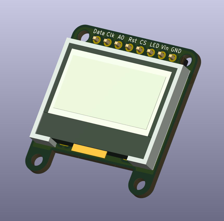
This is a breakout board for the ERC12864FSF-11 COG (Chip On Glass) LCD module, a 0.96", 128x64 pixel display using an ST7567 controller and 4-wire SPI an interface. The PCB routes the display's inputs from its 12-pin FFC cable to a breadboard-friendly 2.54mm pin header. It also exposes the backlight LED pins and provides a few discrete components for LCD module.
It was designed to have a form factor (~27x27mm, 4 mounting holes, pin headers) to like the Adafruit 0.96" OLED module and similar 1" displays.
LCD technology differs from the OLED displays commonly found on display boards of this size. LCD should be daylight readable like e-paper, but with simpler hardware and software requirements. However, LCDs may need a backlight in low-light conditions, so the breakout includes connections display's built-in LED with an option for always on operation. Contrast control is through software.
| Parameter | Value |
|---|---|
| Display | ERC12864FSF-11 (128x64, monochrome) |
| Controller | ST7567 |
| Interface | 4-wire SPI |
| Supply voltage | 3.3V only |
| Board size | ~27 x 27mm |
| Mounting | 4x M2 holes |
ArduinoCode/                             Example sketches for ESP32-C3
COGDisplayBreakout.pretty/               Custom footprint library
COGDisplayBreakout.3dmodels/             Custom 3D models
docs/                                    Datasheets, reference designs, tutorials
images/                                  Image assets
step/                                    3D models of the board and a small case
COGDisplayBreakout.kicad_sch             Schematic
COGDisplayBreakout.kicad_pcb             PCB layout
COGDisplayBreakout.kicad_sym             Custom symbol library
README.mdThe KiCad 9 project files are at the repository root.
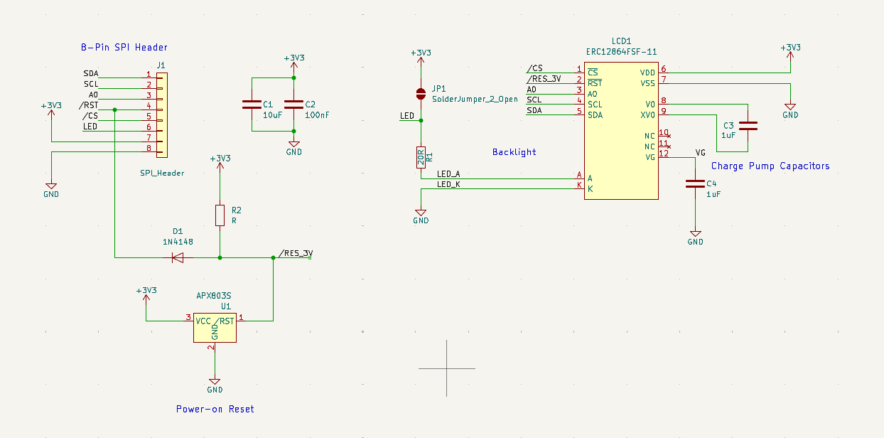
The schematic connects the ERC12864FSF-11 display to an 8-pin SPI header (J1) with supporting passives:
Header pinout (J1 - SPI_Header):
| Pin | Signal | Description |
|---|---|---|
| 1 | SDA | SPI data (MOSI) |
| 2 | SCL | SPI clock |
| 3 | A0 | Data/command select (DC) |
| 4 | /RST | Reset (active low) |
| 5 | /CS | Chip select (active low) |
| 6 | LED | LED control |
| 7 | VDD | +3.3V supply |
| 8 | GND | Ground |
Passive components:
| Ref | Value | Purpose |
|---|---|---|
| R1 | 20R | Backlight LED current-limiting resistor |
| C1 | 10uF | VDD bypass capacitor |
| C2 | 100nF | VDD bypass capacitor |
| C3 | 1uF | Charge pump capacitor (V0 to XV0) |
| C4 | 1uF | Charge pump capacitor (V0 to GND) |
| U1 | APX805S | Power-on reset IC for display /RST line |
The ST7567's built-in voltage booster generates the LCD bias voltage using external capacitors C3, and C4. No regulator or level shifting is included; the board is 3.3V only. Capacitors C1 and C2 are for decoupling. The R1 value was taken from the reference design, but for 10-20 mA LED current it should be about 200 Ohms.
The APX805S monitors VDD and holds the display /RST line low until power is stable, providing a clean power-on reset without requiring a GPIO pin from the host microcontroller. The /RST header pin (pin 4) is still available for external reset if needed.
This is a 2-layer board, ~27x27mm. The display's 12-pin FFC cable (0.6mm pitch) is soldered directly to SMD pads on the back side. The display module mounts flat against the front by means of plastic mounting pins on the display case and the solder tabs for the backlight LED. Four M2 mounting holes at the corners matching similar OLED modules.
The display's 12-pin FFC cable is a non-standard 0.6mm pitch, so must be soldered directly to pads on the breakout PCB.
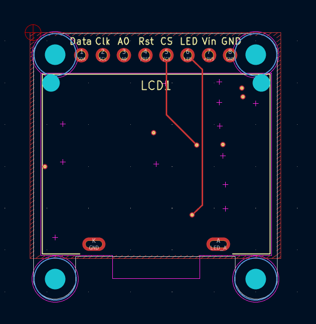 PCB Front (ground plane copper hidden)
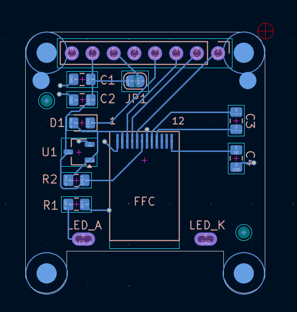 PCB Back
V0.1 (March 2026) - Initial prototype. Known issues: C1 wiring error, missing VG capacitor. See AssemblyNotes.txt for workarounds.
V0.2 (March 2026) - Fixed capacitor circuit. Known issue: backlight A/K pads swapped. See AssemblyNotes.txt.
Gerber files: V0.2 in Gerbers20260323/.
V1.0 (April 2026) - Fixed A/K pads and connected LED control to pin 6. See AssemblyNotes.txt.
Gerber files: V1.0 in Gerbers20260403/.
V1.1 (April 2026) - Added APX805S power-on reset IC for display /RST line. External reset connection via header pin 4 remains optional. Gerbers sent to DigiKey RedBoard fab 2026-04-15.
The project includes a custom schematic symbol, PCB footprint, and 3D model for the ERC12864FSF-11 display module. These are in project-local libraries referenced via sym-lib-table and fp-lib-table.
File: COGDisplayBreakout.kicad_sym
Symbol name: ERC12864FSF-11
12-pin FFC cable (0.6mm pitch, 19mm long) plus 2 backlight pins.
| Pin | Name | Type | Description |
|---|---|---|---|
| 1 | ~{CS} | Input | Chip select (active low) |
| 2 | ~{RST} | Input | Reset (active low) |
| 3 | A0 | Input | Data/command select |
| 4 | SCL | Input | SPI clock |
| 5 | SDA | Input | SPI data (MOSI) |
| 6 | VDD | Power | +3.3V supply |
| 7 | VSS | Power | Ground |
| 8 | V0 | Passive | Contrast voltage (booster output) |
| 9 | XV0 | Passive | Booster capacitor tap |
| 10 | NC | - | Not connected |
| 11 | NC | - | Not connected |
| 12 | VG | Passive | Negative voltage for LCD bias |
| A | A | Passive | Backlight LED anode |
| K | K | Passive | Backlight LED cathode |
Note: The backlight pins (A, K) are separate solder tabs on the display module, not part of the 12-pin FFC cable.
File: COGDisplayBreakout.pretty/ERC12864FSF-11_COG_LCD.kicad_mod
There is a lot going on with this component's footprint:
The 12 SMD pads are a bit longer to allow some play when wrapping the FFC cable around to the back. The pads and oval slot are positioned relative to the stud holes and backlight pins so the FFC cable end is centered on the pads.
Unfortunately, there does not seem to be an FFC/FPC connector available in 12-pin, 6mm pitch so it must be soldered to the PCB. A piece of Kapton tape over the solder joins will provide a bit of strain relief and protection from shorts.
Directory: COGDisplayBreakout.3dmodels/
| File | Format | Description |
|---|---|---|
ERC12864FSF-11.step | STEP | Solid body model for KiCad 3D viewer |
ERC12864FSF-11_COG_LCD.wrl | VRML | Lightweight preview model |
The STEP model is referenced by the footprint and renders in KiCad's 3D viewer and to export the PCB with components as a 3D model.
Example sketches are in ArduinoCode/. The code should run on most modern Arduino board variants with sufficient pins and memory. The code currently targets the Adafruit QT Py ESP32-C3 and uses the U8g2 graphics library.
Install U8g2 via the Arduino IDE Library Manager.
| Display Signal | Header Pin | QT Py Pin | ESP32-C3 GPIO |
|---|---|---|---|
| SCL (clock) | 1 | SCK | 10 |
| SDA (data) | 2 | MO | 7 |
| A0 (DC) | 3 | MI* | 8 |
| /RST | 4 | APX805S on breakout | - |
| /CS | 5 | tied to GND | - |
| LED | 6 | A3 | - |
| GND | 1 | GND | - |
| VDD | 2 | 3V3 | - |
*The MISO pin is repurposed as GPIO since the ERC12864 does not provide data out.
Here are some Arduino sketches that can be run on a XIAO style board like Adafruit's QT Py ESP32-C3 with the connections shown above
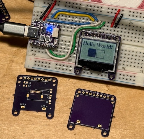
| Sketch | Description |
|---|---|
ERC12864_Hello/ | Minimal hello-world with text and simple graphics. Also blinks the QT Py's NeoPixel. |
ERC12864_SPIDemo/ | AI Port of the manufacturer's C tutorial. Cycles through text, graphics primitives, XBM bitmap, and test patterns. Includes commented-out contrast adjustment code for future button support. |
GraphicsTest/ | U8g2 graphics test suite (from the U8g2 examples, configured for this display). |
ScrollingText/ | U8g2 scrolling text demo (from the U8g2 examples, configured for this display). |
All sketches use the same U8g2 constructor. Identifies the display module by part number and the SPI interface pins. See mappings above.
U8G2_ST7565_ERC12864_ALT_F_4W_SW_SPI u8g2(U8G2_R0,
    /* clock=*/ 10, /* data=*/ 7, /* cs=*/ U8X8_PIN_NONE, /* dc=*/ 8, /* reset=*/ U8X8_PIN_NONE);
ERC12864_ALT - contrast-improved variant for this display_F_ - full framebuffer mode (~1KB RAM)4W_SW_SPI - 4-wire software SPIThe 4-wire HW variants of the U8g2 constructors are intended for the platform's native SPI interface: MOSI, MISO, clock and chip select. Since this device is write only the MISO pin is repurposed for A0 (Data/Command select). The 4-wire SW constructor is used to support this pin mapping but others are possible.
/CS is tied to GND on the breakout board, so the display is always selected and no GPIO is needed for chip select. If sharing the SPI bus with other devices, connect /CS to a GPIO pin and replace U8X8_PIN_NONE with that pin number in the constructor.
/RST is managed by the on-board APX805S power-on reset IC, so no GPIO is needed for reset. If external reset control is required, connect the /RST header pin to a GPIO and replace the reset U8X8_PIN_NONE with that pin number.
Datasheets and reference material are in docs/:
ERC12864-11_Datasheet.pdf - Display module datasheetST7567_V1.7.pdf - Controller IC datasheetERC12864FSF-11_Display.md - Display specifications summaryERC12864FSF-11_SPI_Reference_Design.md - Wiring guide and U8g2 examplesERC12864-11_Tutorial/ - Manufacturer's C code tutorial and interface schematic| Qty | Value | Footprint | References |
|---|---|---|---|
| 4 | MountingHole | MountingHole:MountingHole_2.5mm | H1, H2, H3, H4 |
| 2 | 1uF | Capacitor_SMD:C_0805_2012Metric_Pad1.18x1.45mm_HandSolder | C3, C4 |
| 2 | FIDUCIAL"" | Fiducial:Fiducial_0.5mm_Mask1.5mm | FID1, FID2 |
| 1 | 100nF | Capacitor_SMD:C_0805_2012Metric_Pad1.18x1.45mm_HandSolder | C2 |
| 1 | 10uF | Capacitor_SMD:C_0805_2012Metric_Pad1.18x1.45mm_HandSolder | C1 |
| 1 | 1N4148 | Diode_SMD:D_0805_2012Metric_Pad1.15x1.40mm_HandSolder | D1 |
| 1 | 20R | Resistor_SMD:R_0805_2012Metric_Pad1.20x1.40mm_HandSolder | R1 |
| 1 | APX803S | Package_TO_SOT_SMD:TSOT-23 | U1 |
| 1 | ERC12864FSF-11 | COGDisplayBreakout:ERC12864FSF-11_COG_LCD | LCD1 |
| 1 | R | Resistor_SMD:R_0805_2012Metric_Pad1.20x1.40mm_HandSolder | R2 |
| 1 | SPI_Header | Connector_PinHeader_2.54mm:PinHeader_1x08_P2.54mm_Vertical | J1 |
| 1 | SolderJumper_2_Open | Jumper:SolderJumper-2_P1.3mm_Open_RoundedPad1.0x1.5mm | JP1 |


hoglet67/RGBtoHDMI
Bare-metal Raspberry Pi project that provides pixel-perfect sampling of Retro Computer RGB/YUV video and conversion to HDMI


hackclub/OnBoard
💡 Join 1,000 teenagers and make your first PCB with a $100 grant!

DDeGonge/OS-ARM
This arm is not industrial and it will not be fast, but that is not my goal. But it will hopefully be a very nice looking arm fully capable of 6dof motion, cheap enough to keep it accessable but capable enough to…


It measures 29.2 × 31.8 mm and has 2 copper layers, 1.6 mm thick.
17 parts. The full list of its parts is on this page, with links to each part's symbol and footprint where PCBKit's library has them.
From the bobm123/COGDisplayBreakout repository on GitHub, at the commit this page was made from: the board is COGDisplayBreakout.kicad_pcb and its schematic COGDisplayBreakout.kicad_sch. PCBKit opens the board in the browser, with nothing to install.
Its repository publishes it under the MIT licence: you may reuse it on that licence's terms (keep the author's notice, and for a copyleft licence share your changes alike).