
2 layers89.2 × 82.6 mm
Desktop 50 Pin TopConn
BlueSCSI/BlueSCSI-v2
BlueSCSI v2/Ultra - an open source, open hardware, SCSI emulator using the Pi Pico PR2040 and Pico 2 RP2350
108 parts459GPL-3.0

 bnielsen1965/atarijs-server
Atari floppy drive image server.
Atari rs232 is an open-source printed circuit board by bnielsen1965, from the bnielsen1965/atarijs-server repository on GitHub. It is a 2-layer board of 40.6 × 48.3 mm with 3 parts on 8 nets, routed with 48 tracks and 0 vias.
It is built around the 74HC14. Its parts include 2 connectors and 1 IC. It belongs with the retro computing and games and computers and single-board computers boards of this library.
A NodeJS based server used to emulate Atari floppy drives on the SIO interface and provide a web based user interface for loading of floppy disk images into emulated drives.
WARNING: Always make backup copies of your floppy disk images. When clicking on the save button on a drive control the disk image in memory will overwrite the image file on your hard drive.
What will you need?
Copy the project from github, then use npm install in the project directory to load all the dependencies.
git clone https://github.com/bnielsen1965/atarijs-server.git
cd atarijs-server
npm install
Next edit the config.js file and set the SerialDevice value to your RS232 device that is connected to the Atari SIO interface.
Copy your floppy disk image files into the /atarijs-server/public/images directory where they will be hosted by the server.
And finally use node to start the atarijs-server server.
node index.js
You can now open up the web interface in a web browser by entering the address and port to the host server. I.E. if the atarijs server is running on the same system as the web browser then enter http://localhost:8080/ in the web browser, or if you atarijs server is on a remote host then use the ip address of the host, I.E. http://192.168.0.18:8080.
The user interface is a simple web page with a list of emulated floppy drives on the left and a list of floppy disk image files on the right.
Drag a floppy disk image from the list on the right to input field on an emulated drive on the left and the server will load that image into the emulated drive.
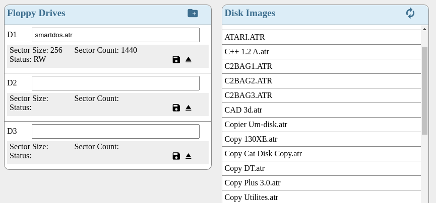
If additional image files are added to the /atarijs-server/public/images folder then the list of floppy disk images can be refreshed by clicking the refresh icon in the upper right corner.
If changes are made to the disk in an emulated drive those changes can be saved back to the image file by clicking on the save disk icon in the emulated drive controls.
The image in an emulated drive can be ejected by clicking on the eject icon on the drives controls.
WARNING: If changes are made to a floppy and it is ejected before saving then the changes will be lost.
The atarijs-server should theoretically work with any RS232 to Atari SIO adapter. The following is the hardware solution that was used during development of atarijs-server.
WARNING: Use this hardware design at your own risk. The RS232 standard specifies voltages that may range +/- 15VDC and depending on the RS232 hardware used you could damage your Atari computer or peripherals.
This circuit is used with the CableCreation USB to RS232 Adapter (FTDI Chipset). A 74HC14 hex inverting Schmitt trigger is used to convert between the 0 to 5 VDC signals on the Atari SIO and the RS232 voltages from the RS232 adapter.
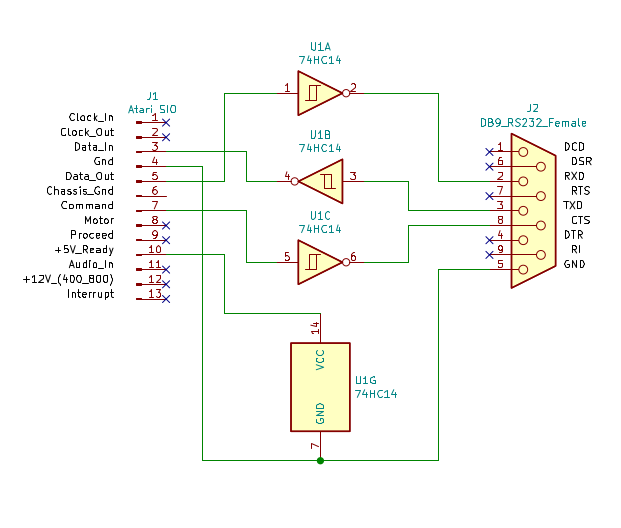
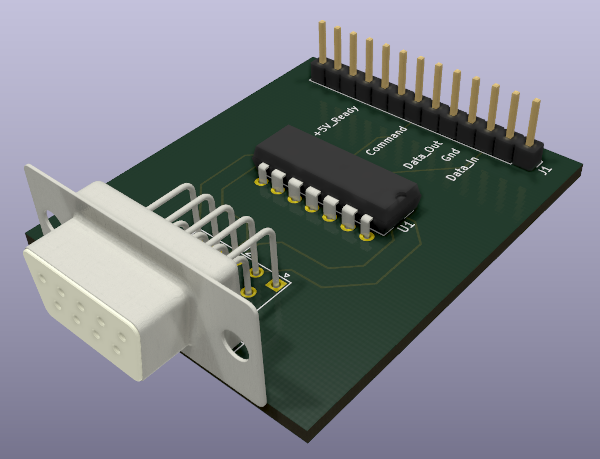
The +5 VDC Ready signal from the Atari SIO is used to power the 74HC14 chip and three of the hex inverter Schmitt trigger gates are used to connect the Atar SIO Data Out to RS232 RxD, SIO Data In to RS232 TxD, and SIO Command to RS232 CTS. The result is a compact PCB...
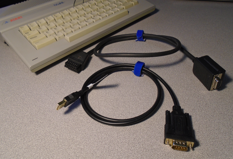
An FTDI based USB to RS-232 cable was used with this 74HC14 based SIO to RS-232
adapter for testing. The signal voltages out of the FTDI based cable were on the
low end of the RS-232 specification so there may not be any risk of over voltage
damage.
| Qty | Value | Footprint | References |
|---|---|---|---|
| 1 | 74HC14 | Package_DIP:DIP-14_W7.62mm | U1 |
| 1 | Atari SIO | Connector_PinHeader_2.54mm:PinHeader_1x13_P2.54mm_Vertical | J1 |
| 1 | DB9_RS232_Female | Connector_Dsub:DSUB-9_Female_Horizontal_P2.77x2.54mm_EdgePinOffset9.40mm | J2 |
It measures 40.6 × 48.3 mm and has 2 copper layers, 1.6 mm thick.
3 parts, built around the 74HC14. The full list of its parts is on this page, with links to each part's symbol and footprint where PCBKit's library has them.
From the bnielsen1965/atarijs-server repository on GitHub, at the commit this page was made from: the board is circuit/atari-rs232/atari-rs232.kicad_pcb. PCBKit opens the board in the browser, with nothing to install.
Its repository states no licence, so its author keeps all rights: ask bnielsen1965 before reusing the design.
BlueSCSI/BlueSCSI-v2
BlueSCSI v2/Ultra - an open source, open hardware, SCSI emulator using the Pi Pico PR2040 and Pico 2 RP2350

keirf/pcb-projects
The old Kickstart switcher documentation is here.

anyshake/explorer
🌏 Detecting seismic wave using 3 geophones and 3-axis accelerometer, pack & send data to AnyShake Observer over RS232 / RS485 serial.

nicolacimmino/PLC-14500
Retro trainer board based on the MC14500 1-bit ICU. The project is OSHW certified and a ready to assemble kit is available on Tindie.


transistorfet/computie
A collection of 68k computer projects, including a unix-like operating system written in C that runs on them

sbstnh/programmable_precision_resistor
A SCPI programmable precision resistor
