2 layers116.8 × 30 mm
Type d
google/mozc-devices
Circuit diagrams and firmware source code for Gboard DIY keyboards
14 parts3kApache-2.0

 BlueJayLouche/remote-relay
sACN/OSC controlled relay
ESP32 Relay is an open-source printed circuit board by BlueJayLouche, from the BlueJayLouche/remote-relay repository on GitHub, published under the MIT licence. It is a 2-layer board of 80 × 60 mm with 14 parts on 7 nets, routed with 15 tracks and 0 vias.
Its parts include 2 resistors, 2 connectors, 1 IC, 1 diode and 1 transistor. It belongs with the home automation and IoT boards and the ESP32 boards of this library.
A basic 2-layer carrier PCB for the AromaDiffuser controller: 12 V in → buck → ESP32-C3 Super Mini → transistor → relay → pump out.
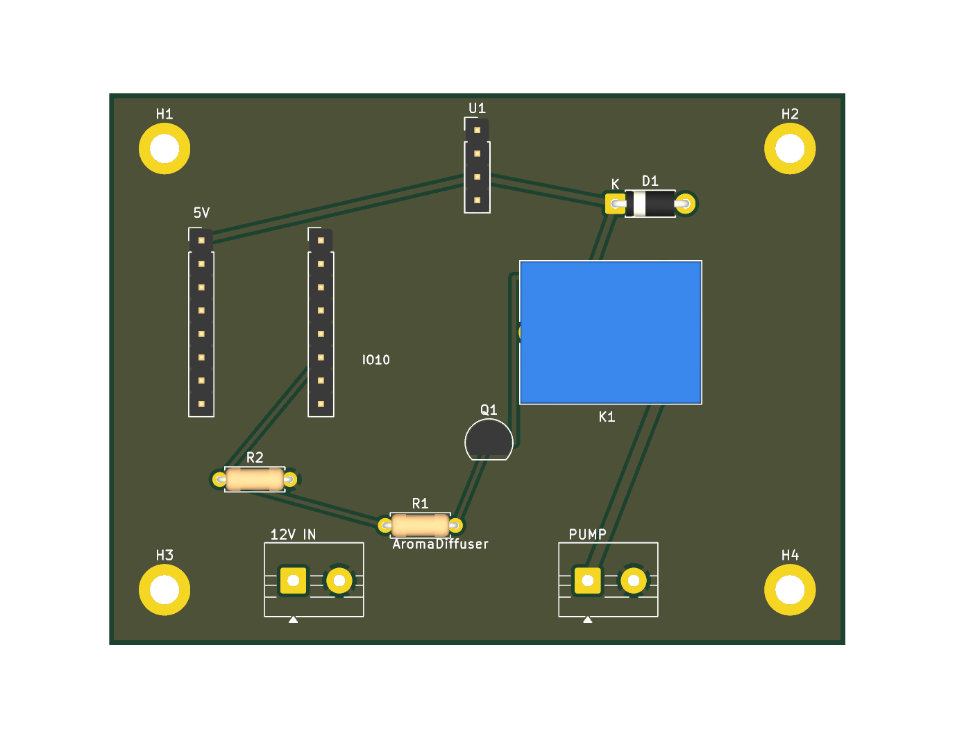
~80 × 60 mm, 2-layer, fully routed with a GND pour. The relay is a dry SPDT contact, so the switched side works for an AC or DC pump (subject to the mains caveat below).
Three scripts, run in order with KiCad's bundled Python. KiCad has no schematic
Python API, so each .kicad_* is written directly; the schematic and PCB are kept
consistent by sharing the same net names.
KPY=/Applications/KiCad/KiCad.app/Contents/Frameworks/Python.framework/Versions/Current/bin/python3
$KPY gen_board.py    # footprints, nets, GND pour, outline, mounting holes
$KPY gen_sch.py      # matching schematic (symbols + net labels)
$KPY gen_routes.py   # route the 6 non-GND nets
Verified with kicad-cli: schematic ERC clean, PCB DRC clean (0 violations,
0 unrouted), and the schematic netlist matches the PCB. See schematic.pdf.
The PCB carries its own netlist (no sheet-to-board link). If you edit the schematic and want to push changes, re-run
gen_routes.pyrather than KiCad's "Update PCB from schematic".
It's DRC/ERC-clean, but still bench-verify the part-specific assumptions:
A1/A2 are 2× 1×8 headers, rows 13 mm apart. "Super
Mini" clones vary — measure yours and adjust the A1/A2 X positions in
gen_board.py if needed before fab.U1 is an MP1584 module on a 1×4 header — set its trimmer to 5.0 V
before connecting the C3.schematic.pdf and the PCB)| Net | Connections |
|---|---|
| +12V | J1.1 (12V IN), U1.1 (buck VIN+), K1.1 (relay COM) |
| +5V | U1.3 (buck VOUT+), A1.1 (C3 5V), K1.2 (coil+), D1.1 (diode K) |
| GND | J1.2, U1.2, U1.4, A1.2 (C3 GND), Q1.1 (emitter), R2.2, J2.2, H1–H4, pour |
| CTRL_IO10 | A2.6 (C3 GPIO10), R1.1, R2.1 |
| Q_BASE | R1.2, Q1.2 (base) |
| COIL_DRV | Q1.3 (collector), K1.5 (coil−), D1.2 (diode A) |
| PUMP | K1.3 (relay NO), J2.1 |
R2 (10 k, GPIO10→GND) holds the transistor off during boot/reset → pump off at
power-up. D1 is the coil flyback (band/cathode to +5 V).
| Ref | Part | Notes |
|---|---|---|
| A1, A2 | 2× 1×8 socket header, 2.54 mm | seat the ESP32-C3 Super Mini |
| U1 | MP1584 buck module + 1×4 header | 12 V → 5.0 V |
| K1 | SPDT relay, 5 V coil | SRD-05VDC-SL-C (or pin-compatible) |
| Q1 | NPN BJT, TO-92 | PN2222A (E-B-C) |
| D1 | diode, DO-41 | 1N4007 |
| R1 | resistor | 1 kΩ (base) |
| R2 | resistor | 10 kΩ (pulldown) |
| J1, J2 | 2-pin screw terminal, 5 mm | J1 = 12V IN, J2 = PUMP |
| H1–H4 | M3 mounting holes | grounded |
Export gerbers:
/Applications/KiCad/KiCad.app/Contents/MacOS/kicad-cli pcb export gerbers --output gerbers/ ESP32_Relay.kicad_pcb
/Applications/KiCad/KiCad.app/Contents/MacOS/kicad-cli pcb export drill   --output gerbers/ ESP32_Relay.kicad_pcb
…or just upload ESP32_Relay.kicad_pcb directly to JLCPCB/PCBWay.
| Qty | Value | Footprint | References |
|---|---|---|---|
| 4 | MountingHole_3.2mm_M3_DIN965_Pad | MountingHole_3.2mm_M3_DIN965_Pad | H1, H2, H3, H4 |
| 1 | 10k pulldown | R_Axial_DIN0207_L6.3mm_D2.5mm_P7.62mm_Horizontal | R2 |
| 1 | 12V IN | TerminalBlock_MaiXu_MX126-5.0-02P_1x02_P5.00mm | J1 |
| 1 | 1N4007 (band=K -> +5V) | D_DO-41_SOD81_P7.62mm_Horizontal | D1 |
| 1 | 1k base | R_Axial_DIN0207_L6.3mm_D2.5mm_P7.62mm_Horizontal | R1 |
| 1 | 5V relay SRD-05VDC-SL-C | Relay_SPDT_SANYOU_SRD_Series_Form_C | K1 |
| 1 | C3 L:5V,GND,3V3,IO4,IO3,IO2,IO1,IO0 | PinHeader_1x08_P2.54mm_Vertical | A1 |
| 1 | C3 R:IO5,IO6,IO7,IO8,IO9,IO10,RX,TX | PinHeader_1x08_P2.54mm_Vertical | A2 |
| 1 | MP1584 12V->5V: VIN+,VIN-,VOUT+,VOUT- | PinHeader_1x04_P2.54mm_Vertical | U1 |
| 1 | PN2222A E-B-C | TO-92_Inline | Q1 |
| 1 | PUMP | TerminalBlock_MaiXu_MX126-5.0-02P_1x02_P5.00mm | J2 |
It measures 80 × 60 mm and has 2 copper layers, 1.6 mm thick.
14 parts. The full list of its parts is on this page, with links to each part's symbol and footprint where PCBKit's library has them.
From the BlueJayLouche/remote-relay repository on GitHub, at the commit this page was made from: the board is ESP32_Relay/ESP32_Relay.kicad_pcb and its schematic ESP32_Relay/5vAroma/5vAroma.kicad_sch. PCBKit opens the board in the browser, with nothing to install.
Its repository publishes it under the MIT licence: you may reuse it on that licence's terms (keep the author's notice, and for a copyleft licence share your changes alike).
google/mozc-devices
Circuit diagrams and firmware source code for Gboard DIY keyboards


hackclub/OnBoard
💡 Join 1,000 teenagers and make your first PCB with a $100 grant!


Twotoz/C5VRX
Ultra-minimal, zero-CPU 5.8 GHz analog FPV video receiver using ESP32-C5 Wi-Fi 6 PHY MODEM_DIAG, BitScrambler WBFM demodulation & resistor DAC CVBS

