
4 layers67.7 × 10.5 mm

Hardware for the Bloop NFC Scanner
NFC2USB is an open-source printed circuit board by bloop-box, from the bloop-box/nfc-scanner-hardware repository on GitHub, published under the BSD-2-Clause licence. It is a 4-layer board of 41 × 40 mm with 44 parts on 56 nets, routed with 237 tracks and 41 vias.
It is built around the RP2040, W25Q32JVUUIQ and AMS1117-3.3. Its parts include 18 capacitors, 8 resistors, 4 ICs, 2 diodes and 2 switches. It belongs with the radio and wireless boards and the RP2040 boards of this library.


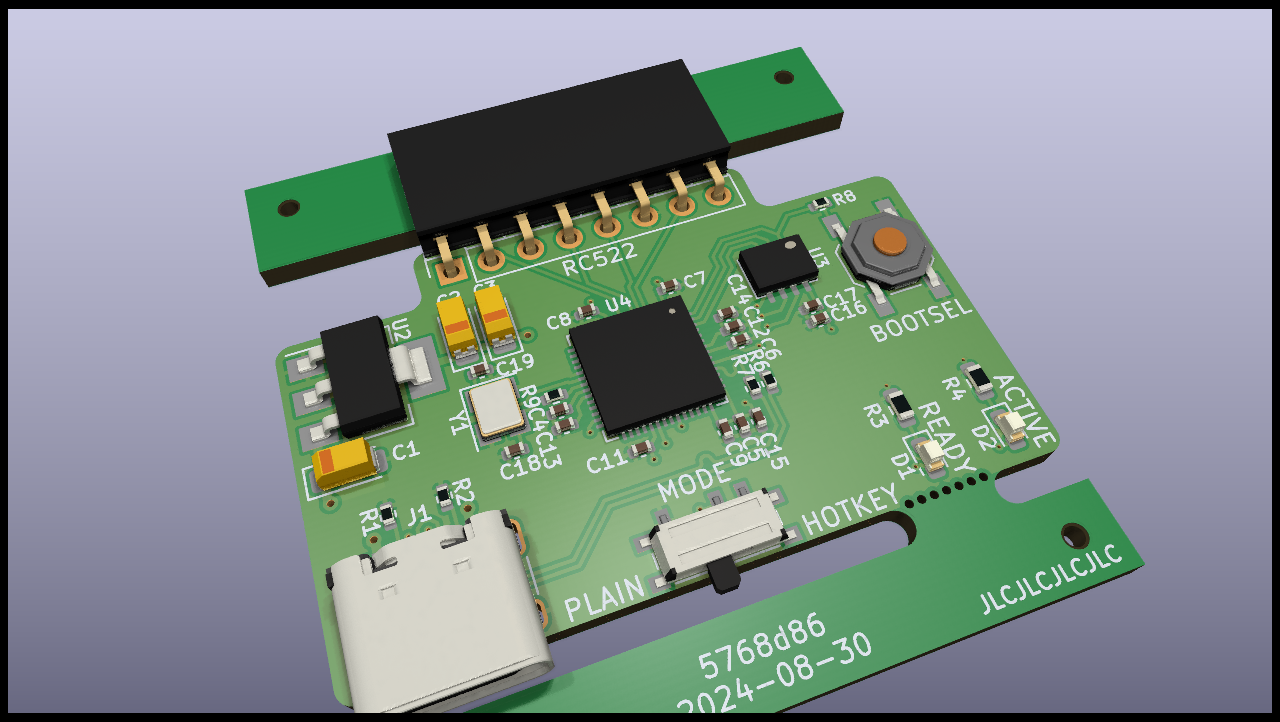
Connect an RC522 based NFC-Reader to your computer using USB
The project is based around a Raspberry Pi RP2040 microcontroller. It would have been possible to solve this with a much simpler controller but availability and pricing at the time of development as well as ease of use made the RP2040 with built in USB the best choice.
The board is designed using KiCAD 6 with production and assembly by JLCPCB in mind. All parts are selected to be available from JLCPCB at the time of writing and as many parts as possible are used from their basic library.
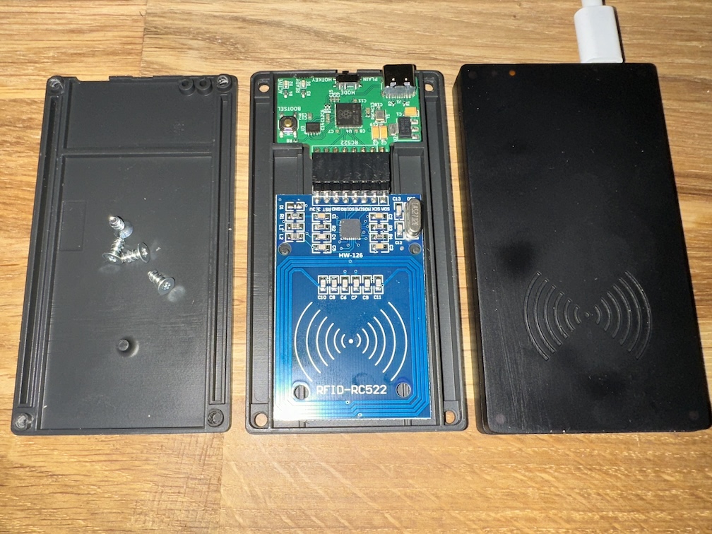
A simple case design can be found in the case subfolder. It fits when the two boards are connected with standard angled 2.54mm pitch connectors as seen in the picture.
The two halves can be connected with self-tapping, countersunk M3x6 screws
| Qty | Value | Footprint | References |
|---|---|---|---|
| 10 | 100n | Capacitor_SMD:C_0402_1005Metric | C4, C5, C6, C7, C8, C9, C11, C12, C13, C17 |
| 3 | 10u | Capacitor_Tantalum_SMD:CP_EIA-3216-18_Kemet-A | C1, C2, C3 |
| 3 | 1u | Capacitor_SMD:C_0402_1005Metric | C14, C15, C16 |
| 2 | 15p | Capacitor_SMD:C_0402_1005Metric | C18, C19 |
| 2 | 1k | Resistor_SMD:R_0402_1005Metric | R8, R9 |
| 2 | 270R | Resistor_SMD:R_0603_1608Metric | R3, R4 |
| 2 | 27R | Resistor_SMD:R_0402_1005Metric | R6, R7 |
| 2 | 5k1 | Resistor_SMD:R_0402_1005Metric | R1, R2 |
| 2 | VAL** | Panelization:mouse-bite-2x5mm-slot-onesided-v2 | mouse-bite-2mm-slot, mouse-bite-2mm-slot |
| 1 | 12MHz | Crystal:Crystal_SMD_3225-4Pin_3.2x2.5mm | Y1 |
| 1 | ACT | LED_SMD:LED_0603_1608Metric | D2 |
| 1 | AMS1117-3.3 | Package_TO_SOT_SMD:SOT-223-3_TabPin2 | U2 |
| 1 | BOOTSEL | Button_Switch_SMD:SW_SPST_TL3342 | SW1 |
| 1 | LOGO | My_Footprints:CutieMark5mmInverted | G*** |
| 1 | MODE | Button_Switch_SMD:SW_SPDT_PCM12 | SW2 |
| 1 | NFCModuleRC522 | Connector_PinSocket_2.54mm:PinSocket_1x08_P2.54mm_Vertical | U1 |
| 1 | RDY | LED_SMD:LED_0603_1608Metric | D1 |
| 1 | RP2040 | Package_DFN_QFN:QFN-56-1EP_7x7mm_P0.4mm_EP3.2x3.2mm | U4 |
| 1 | USB_C_USB2.0 | Connector_USB:USB_C_Receptacle_HRO_TYPE-C-31-M-12 | J1 |
| 1 | W25Q32JVUU | My_Footprints:USON8 (3x4) | U3 |
The 39 most common of 44 parts.
It measures 41 × 40 mm and has 4 copper layers, 1.6 mm thick.
44 parts, built around the RP2040, W25Q32JVUUIQ and AMS1117-3.3. The full list of its parts is on this page, with links to each part's symbol and footprint where PCBKit's library has them.
From the bloop-box/nfc-scanner-hardware repository on GitHub, at the commit this page was made from: the board is pcb/NFC2USB.kicad_pcb and its schematic pcb/NFC2USB.kicad_sch. PCBKit opens the board in the browser, with nothing to install.
Its repository publishes it under the BSD-2-Clause licence: you may reuse it on that licence's terms (keep the author's notice, and for a copyleft licence share your changes alike).

piit79/Frood
Microcontroller module based on a RP2040 compatible with Elite-C / nice!nano


TweetyDaBird/Fat-Chameleon
A Grid Ortho keyboard for BM40, JJ40/JJ50 cases inspired by Planck and Preonic

Kelvin-Ziqi-Zhao/drone-current-sensor-board
High current sensor board for battery+capacitor power supply system

TweetyDaBird/Skinny-Chameleon
The Skinny Chameleon is a grid type orthogonal keyboard made to be a direct drop-in for the Preonic's and Planck's PCB's.

