2 layers143.5 × 115.5 mm
SofleKeyboard
josefadamcik/SofleKeyboard
A split keyboard based on Lily58, Crkbd and Helix keyboards
89 parts2.6k

 Bloho/bloho-star-badge
A star-shaped, light-sensitive blinking LED PCB badge designed for Hack Club Solder.
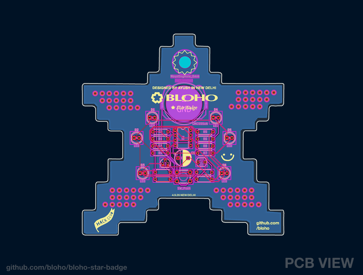
Bloho star badge is an open-source printed circuit board by Bloho, from the Bloho/bloho-star-badge repository on GitHub. It is a 2-layer board of 100 × 99.7 mm with 89 parts on 17 nets, routed with 148 tracks and 0 vias.
Its parts include 13 resistors, 6 diodes, 1 capacitor, 1 IC and 1 transistor. It belongs with the lEDs and displays boards of this library.
A star-shaped, light-sensitive blinking LED PCB badge designed for Hack Club Solder.
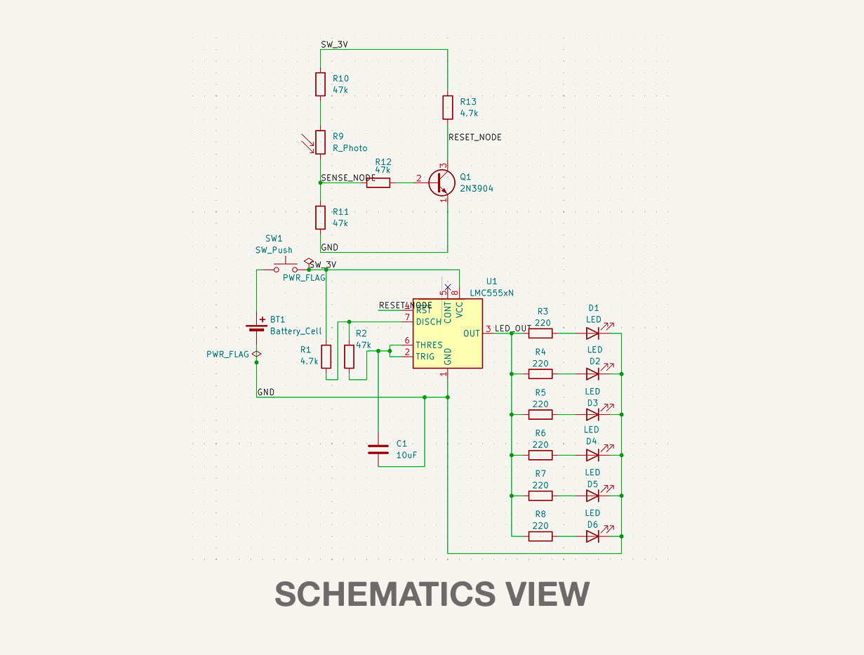
The board uses an LMC555 timer in astable mode to blink six LEDs simultaneously. Alongside the oscillator, a photoresistor and 2N3904 transistor form a light-sensing circuit connected to the 555's RESET pin, allowing the LEDs to automatically disable in bright light.
The badge is powered by a CR2032 coin cell and uses through-hole components for easy hand assembly.
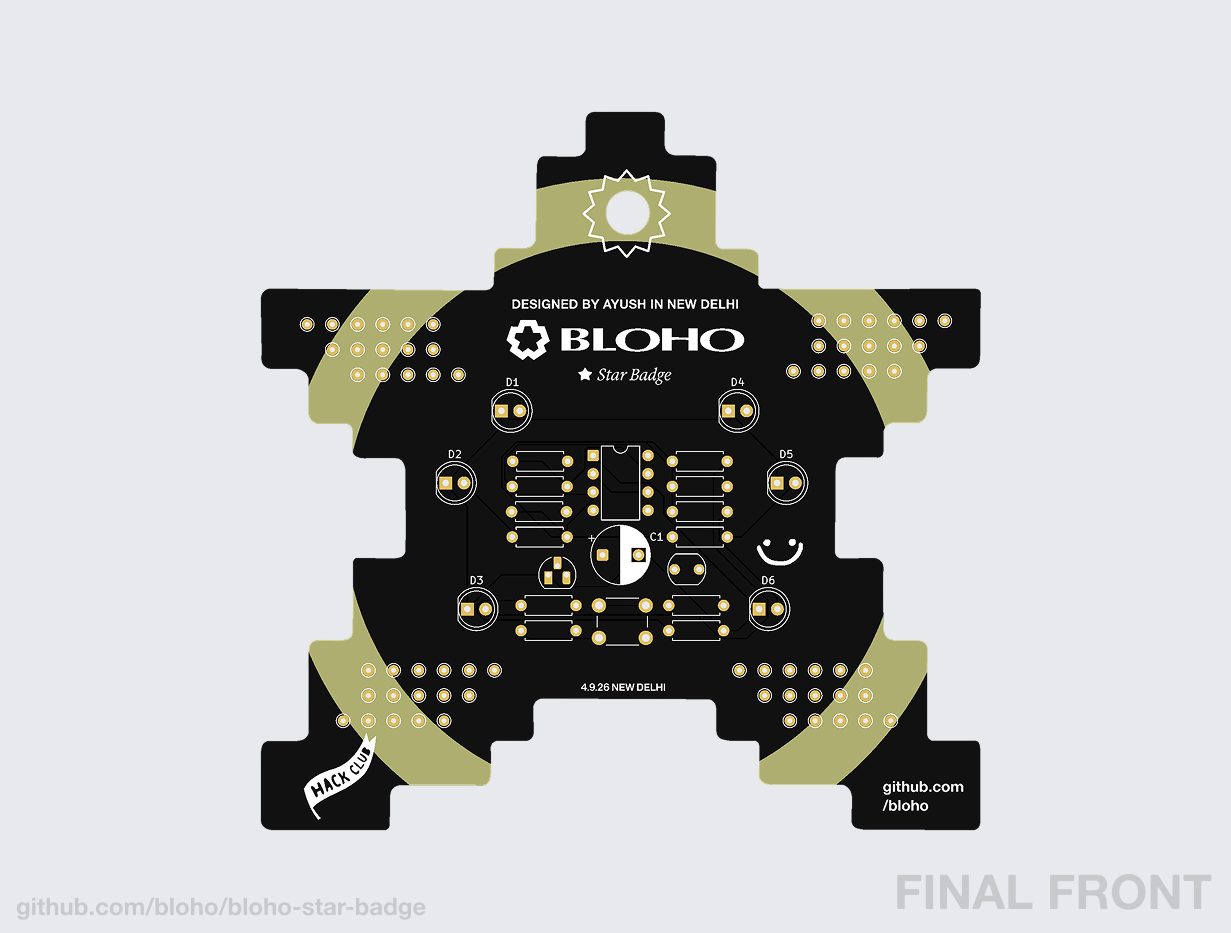
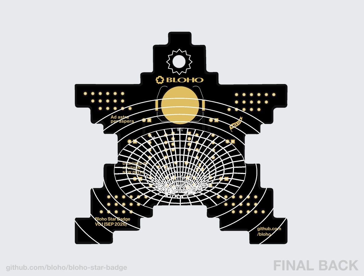
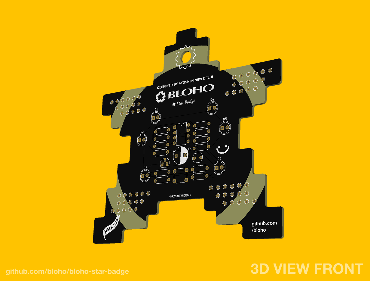
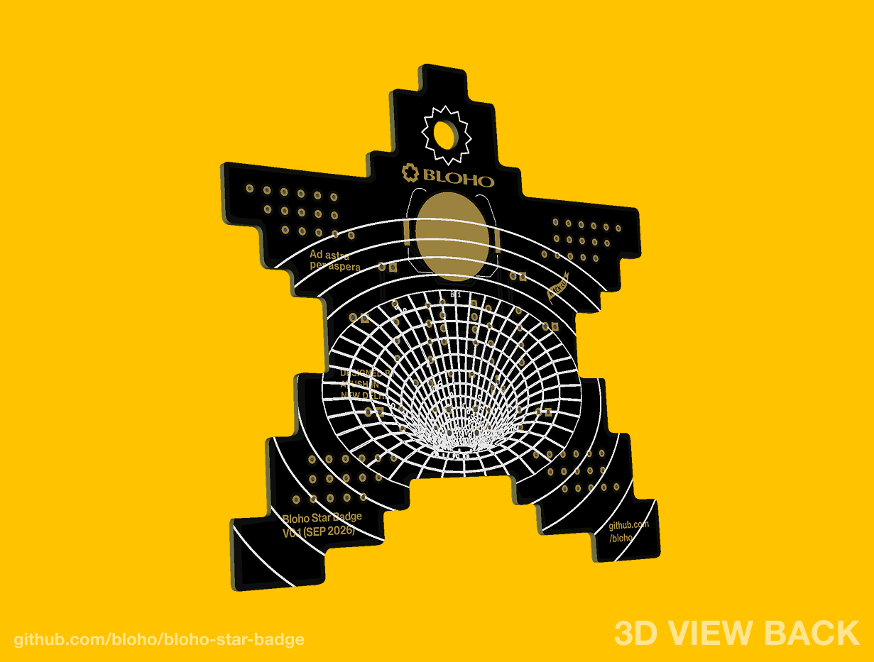
The complete circuit was simulated in Falstad CircuitJS before fabrication.
The simulation was used to verify:
Open the interactive Falstad simulation
The main circuit is based around an LMC555 timer configured as an astable oscillator.
The timing network uses:
The capacitor repeatedly charges and discharges through the timing resistors, causing the 555 output to oscillate.
The output drives six LEDs in parallel.
Each LED has its own 220 Ω current-limiting resistor.
A photoresistor and 2N3904 NPN transistor are used to control the RESET input of the 555 timer.
The light-sensing section uses:
R10, the LDR, and R11 form the sensing network.
The resulting SENSE_NODE drives the base of Q1 through R12.
Q1's collector is connected to the 555's RESET_NODE, while R13 pulls RESET toward the 3 V supply.
When enough light reaches the photoresistor, Q1 activates and pulls the RESET pin low. This disables the 555 oscillator and stops the LEDs from blinking.
In darker conditions, Q1 releases the RESET line and the 555 is allowed to oscillate normally.
The complete circuit operates from a 3 V CR2032 coin cell.
A 6 mm momentary pushbutton is used as the main power control for the badge.
| Reference | Component | Quantity | Value / Part |
|---|---|---|---|
| U1 | 555 Timer | 1 | LMC555 |
| D1-D6 | LEDs | 6 | 5 mm LED |
| R3-R8 | LED resistors | 6 | 220 Ω |
| R1 | Timing resistor | 1 | 4.7 kΩ |
| R2 | Timing resistor | 1 | 47 kΩ |
| C1 | Timing capacitor | 1 | 10 µF |
| R9 | Photoresistor | 1 | LDR |
| R10 | Sensor resistor | 1 | 47 kΩ |
| R11 | Sensor resistor | 1 | 47 kΩ |
| R12 | Transistor base resistor | 1 | 47 kΩ |
| R13 | RESET pull-up resistor | 1 | 4.7 kΩ |
| Q1 | NPN transistor | 1 | 2N3904 |
| SW1 | Pushbutton | 1 | 6 mm THT |
| BT1 | Battery holder | 1 | CR2032 holder |
| - | Battery | 1 | CR2032 3 V |
The PCB was designed in KiCad as a 2-layer through-hole board.
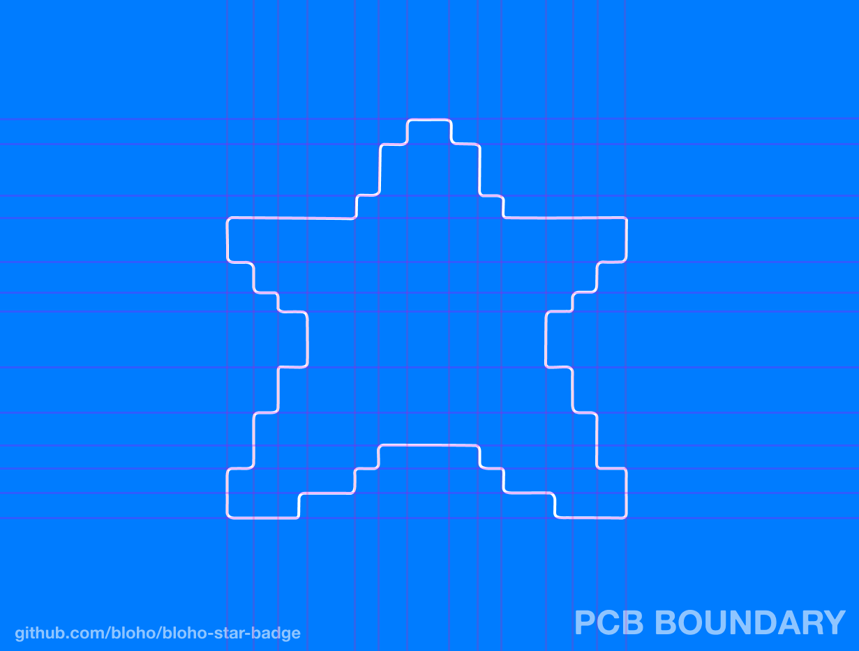
The electronics were arranged inside a custom star-shaped outline while leaving space for decorative artwork and the lanyard hole.
The final board uses:
The routed board was checked using KiCad's Design Rules Checker with:
The goal was to make the PCB itself part of the artwork rather than treating it as only a circuit board.
The board uses a custom star-shaped outline, decorative holes, custom silkscreen graphics, typography, and additional PCB-layer artwork integrated around the electronics.
Selected artwork elements use copper and solder-mask geometry to create metallic details directly as part of the fabricated PCB.
The electronics and visual elements were arranged together while keeping the board suitable for through-hole hand soldering.
Manufacturing files are available in the gerbers/ directory.
They include:
The original KiCad project files are also included so the board can be inspected, modified, or regenerated.
Aaaaand yes, I used AI to format README.md lol.
Mail me at ayush@bloho.space if you have anything to ask, or say!
| Qty | Value | Footprint | References |
|---|---|---|---|
| 6 | 220 | Resistor_THT:R_Axial_DIN0207_L6.3mm_D2.5mm_P7.62mm_Horizontal | R3, R4, R5, R6, R7, R8 |
| 6 | LED | LED_THT:LED_D5.0mm | D1, D2, D3, D4, D5, D6 |
| 4 | 47k | Resistor_THT:R_Axial_DIN0207_L6.3mm_D2.5mm_P7.62mm_Horizontal | R2, R10, R11, R12 |
| 2 | 4.7k | Resistor_THT:R_Axial_DIN0207_L6.3mm_D2.5mm_P7.62mm_Horizontal | R1, R13 |
| 1 | 10uF | Capacitor_THT:CP_Radial_D8.0mm_P5.00mm | C1 |
| 1 | 2N3904 | Package_TO_SOT_THT:TO-92L_HandSolder | Q1 |
| 1 | Battery_Cell | Battery:BatteryHolder_Keystone_3034_1x20mm | BT1 |
| 1 | LMC555xN | Package_DIP:DIP-8_W7.62mm | U1 |
| 1 | R_Photo | OptoDevice:R_LDR_5.1x4.3mm_P3.4mm_Vertical | R9 |
| 1 | SW_Push | Button_Switch_THT:SW_PUSH_6mm | SW1 |
The 24 most common of 89 parts.
josefadamcik/SofleKeyboard
A split keyboard based on Lily58, Crkbd and Helix keyboards


tebl/BulkyMIDI-32
A HW build of the MT32-PI project, allowing you to emulate a Roland MT-32 using a Raspberry Pi. Includes enough additional modules to build a MIDI-mountain as well as adapters for connecting to most things retro.
It measures 100 × 99.7 mm and has 2 copper layers, 1.6 mm thick.
89 parts. The full list of its parts is on this page, with links to each part's symbol and footprint where PCBKit's library has them.
From the Bloho/bloho-star-badge repository on GitHub, at the commit this page was made from: the board is bloho-star-badge.kicad_pcb and its schematic bloho-star-badge.kicad_sch. PCBKit opens the board in the browser, with nothing to install.
Its repository states no licence, so its author keeps all rights: ask Bloho before reusing the design.