2 layers123 × 87.5 mm
FastLOGIC
Neumi/fastLOGIC
An affordable Arduino-based board designed for straightforward (industrial) logic control, ideal for building small-scale automation and control solutions.
180 parts23MIT

 Blank127/FireAlarm
A temperature monitoring and alarm system built on a custom PCB. The DS18B20 sensor continuously reads ambient temperature and displays it on a 4-digit 7-segment display.
PCB Final is an open-source printed circuit board by Blank127, from the Blank127/FireAlarm repository on GitHub, published under the MIT licence. It is a 4-layer board of 160 × 82 mm with 37 parts on 73 nets, routed with 182 tracks and 14 vias.
It is built around the DS18B20 and AMS1117-3.3. Its parts include 9 capacitors, 6 resistors, 4 connectors, 3 ICs and 2 diodes. It belongs with the STM32 boards of this library.


CMPE2700 — PCB Design Project STM32G0B1RETx · DS18B20 · DFRobot Gravity 7-Segment Displays · USB-C Powered
A temperature monitoring and alarm system built on a custom PCB. The DS18B20 sensor continuously reads ambient temperature and displays it on a 4-digit 7-segment display. When the temperature exceeds a configurable threshold, an alarm LED activates. The alarm must be manually acknowledged by pressing the onboard button.
A second 7-segment display shows the current alarm threshold for reference at all times.
| Component | Description |
|---|---|
| STM32G0B1RETx | Main microcontroller |
| DS18B20 | 1-Wire digital temperature sensor |
| AMS1117-3.3 | LDO voltage regulator, steps down 5 V → 3.3 V |
| DFRobot Gravity 4-Digit LED Display (×2) | TM1650-based 7-segment displays over I2C |
| USB-C Connector | Board power input (5 V) |
| SWD Header | STM32 programming and debug interface |
| Tactile Button | Alarm acknowledge / reset |
| External LED | Alarm indicator |
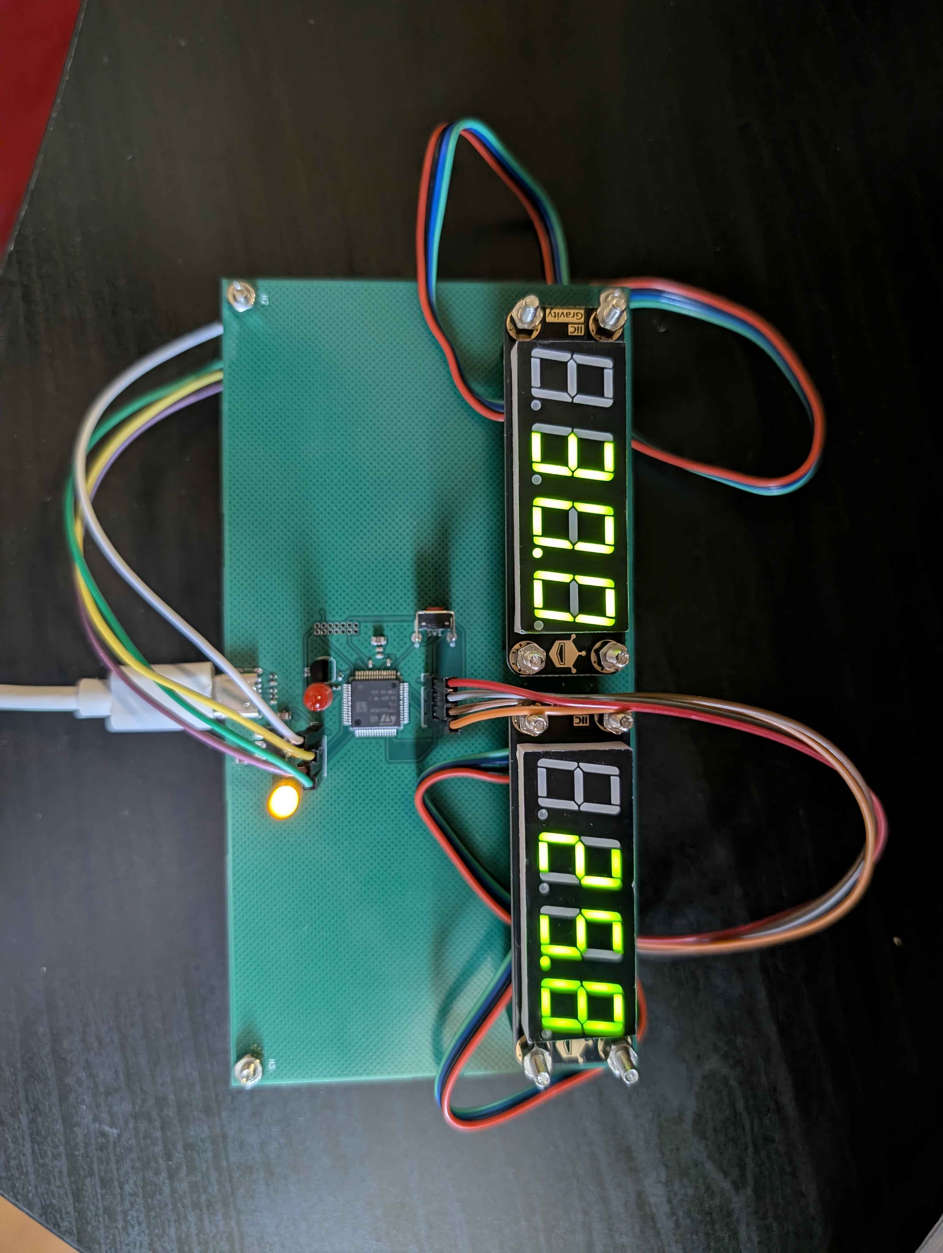
📷 PCB photo — upload a JPG/PNG version of the image to add it here
⚠️ Workaround required — jumper wires needed
The I2C headers J1 and J2 were routed with the following pinout:
PCB Header (J1/J2): 5V · GND · SDA · SCLHowever, the mating female connectors on the DFRobot Gravity displays use:
Display Connector: 5V · GND · SCL · SDAThe SDA and SCL lines are swapped between the PCB header and the display connector. As a result, the displays cannot be plugged in directly — they will not communicate.
Fix: Use jumper wires to cross SDA and SCL between the header and the display connector before plugging in.
This will be corrected in the next PCB revision by swapping the SDA/SCL positions on J1 and J2 in the schematic.
The firmware is written in C using the STM32 HAL library and structured across three STM32CubeIDE projects:
| Project | Description |
|---|---|
Temperature sensor/ | DS18B20 driver development and test |
SevenSeg/ | TM1650 7-segment display driver development and test |
Temperature alert system/ | Final integrated alarm application |
Firmware/
├── Temperature sensor/         # DS18B20 test project
├── SevenSeg/                   # 7-segment display test project
└── Temperature alert system/   # Final alarm application
Hardware/
├── PCB_Final.kicad_pcb         # PCB layout
├── PCB_Final.kicad_sch         # Schematic
└── PCB_Final.kicad_pro # KiCad project file| Signal | STM32 Pin | Notes |
|---|---|---|
| 1-Wire Data | PA (one_wire_data) | DS18B20 with 4.7 kΩ pull-up |
| I2C1 SDA/SCL | I2C1 | Display 1 — current temperature |
| I2C2 SDA/SCL | I2C2 | Display 2 — alarm threshold |
| Alarm LED | PA (ext_led) | Active high |
| Button (B1) | PC13 | Active low, internal pull-up |
| Green LED | PA5 | Onboard status/heartbeat |
| USART2 TX/RX | PA2 / PA3 | Debug output at 115200 baud |
Aldrich Dias — CMPE2750, 2026
| Qty | Value | Footprint | References |
|---|---|---|---|
| 4 | Display1_Mount | MountingHole:MountingHole_3.2mm_M3 | H5, H6, H7, H8 |
| 4 | Display2_Mount | MountingHole:MountingHole_3.2mm_M3 | H9, H10, H11, H12 |
| 4 | PCB_Corner_Mounts | MountingHole:MountingHole_3.2mm_M3 | H1, H2, H3, H4 |
| 3 | 100n | Capacitor_SMD:C_0402_1005Metric | C1, C2, C6 |
| 3 | 10u | Capacitor_SMD:C_0805_2012Metric | C5, C7, C8 |
| 2 | 5.1k | Resistor_SMD:R_0402_1005Metric | R4, R5 |
| 1 | 10n | Capacitor_SMD:C_0402_1005Metric | C4 |
| 1 | 1M | Resistor_SMD:R_0402_1005Metric | R6 |
| 1 | 1k | Resistor_SMD:R_0402_1005Metric | R3 |
| 1 | 1u | Capacitor_SMD:C_0402_1005Metric | C3 |
| 1 | 330 | Resistor_SMD:R_0402_1005Metric | R2 |
| 1 | 4.7k | Resistor_SMD:R_0402_1005Metric | R1 |
| 1 | 4.7n | Capacitor_SMD:C_0402_1005Metric | C9 |
| 1 | AMS1117-3.3 | Package_TO_SOT_SMD:SOT-223-3_TabPin2 | U3 |
| 1 | Alarm_LED | LED_THT:LED_D3.0mm | D1 |
| 1 | Conn_ST_STDC14 | Connector_PinHeader_1.27mm:PinHeader_2x07_P1.27mm_Vertical | J3 |
| 1 | DISP_CURRENT | Connector_PinHeader_2.54mm:PinHeader_1x04_P2.54mm_Vertical | J1 |
| 1 | DISP_THRESHOLD | Connector_PinHeader_2.54mm:PinHeader_1x04_P2.54mm_Vertical | J2 |
| 1 | DS18B20 | Package_TO_SOT_THT:TO-92_Inline | U1 |
| 1 | PWR_LED | LED_THT:LED_D3.0mm | D2 |
| 1 | STM32G0B1RETx | Package_QFP:LQFP-64_10x10mm_P0.5mm | U2 |
| 1 | SW_Push | Button_Switch_THT:SW_Tactile_SPST_Angled_PTS645Vx31-2LFS | SW1 |
| 1 | USB_C_Receptacle_PowerOnly_6P | Connector_USB:USB_C_Receptacle_GCT_USB4125-xx-x-0190_6P_TopMnt_Horizontal | J4 |
It measures 160 × 82 mm and has 4 copper layers, 1.6 mm thick.
37 parts, built around the DS18B20 and AMS1117-3.3. The full list of its parts is on this page, with links to each part's symbol and footprint where PCBKit's library has them.
From the Blank127/FireAlarm repository on GitHub, at the commit this page was made from: the board is Hardware/PCB_Final.kicad_pcb and its schematic Hardware/PCB_Final.kicad_sch. PCBKit opens the board in the browser, with nothing to install.
Its repository publishes it under the MIT licence: you may reuse it on that licence's terms (keep the author's notice, and for a copyleft licence share your changes alike).
Neumi/fastLOGIC
An affordable Arduino-based board designed for straightforward (industrial) logic control, ideal for building small-scale automation and control solutions.

Manawyrm/CMM2-JLC
Colour Maximite 2 - unofficial PCB design for automated assembly

Vedatori/Time-O-Mat
Addressable LED clock kit aimed for usage in STEM education. The ultimate solution to time telling...


klaus-liebler/labathome
Der kleine Bruder von lab@home. Ermöglicht das Experimentieren mit PT1...PTn-Gliedern, die intern als RC-Kombination (entkoppelt über Operationsverstärker) ausgeführt sind.


Vedatori/PaLampa
Mechanickou část lze rozdělit na dvě hlavní části - spodní krabici a horní lampu. Vnější části krabice jsou vyřezány z překližky na laserové řezačce a obsahují zámkové západky.

SkullKill/ESP32-Wall-Clock-PCB
ESP32 based 30cm Wall Mounted Clock. WiFi, NTP, SNMP, web interface, MicroUsb, Type-C, HG3613 Retrofit