
2 layers102.9 × 87.6 mm

 blackbit42/MAUreene_82262
Token Ring MAU
Token Ring MAU is an open-source printed circuit board by blackbit42, from the blackbit42/MAUreene_8226 repository on GitHub, published under the CERN-OHL-P-2.0 licence. It is a 4-layer board of 100 × 70 mm with 62 parts on 67 nets, routed with 528 tracks and 57 vias.
It is built around the H11A1. Its parts include 28 resistors, 13 capacitors, 4 transistors, 4 connectors and 3 ICs.
[!WARNING] The current revision of the board is not functional. Build only if you want to work on fixing it.
MAUreene 8226 is a Token Ring (IEEE 802.5) Media Access Unit (MAU) that is inspired by the IBM 8226. For the most part, it is a reproduction of the IBM 8226, reduced to 2 'lobes', which is Token Ring lingo for what is known as a port in the context of other network technologies.
Token Ring is an interesting LAN technology. NICs are all over common auction sites and can be had cheaply, though MAUs are hard to come by. The intent of this project is to enable inclined people to play with Token Ring more easily.
In an ethernet network you can nowadays connect two arbitrary devices with each other back to back without thinking about it, due to to the power of Auto MDI-X. Earlier you could use so-called 'crossover' cables. Unfortunately Token Ring doesn't support such a mode of interconnection, as a NIC goes through a mildly elaborated attachment process with a MAU. A mode where two hosts talk directly to each other doesn't exist, see this.
| Original 8226 | Lobe 1 | Lobe 2 | Package | Type | Measured value1 | Marking | Remarks |
|---|---|---|---|---|---|---|---|
| R2 | R1 | R21 | 0805 | 4.8k | 4871 | ||
| R10 | R2 | R22 | 0603 | -None- | -None- | Opto-coupler biasing, not populated | |
| R34 | R3 | R23 | 0603 | 0.3 | 000 | RJ45 termination | |
| R35 | R4 | R24 | 0603 | 0.3 | 000 | RJ45 termination | |
| R44 | R5 | R25 | 0603 | 100 | 101 | ||
| R52 | R6 | R26 | 0603 | 100 | 101 | ||
| R60 | R7 | R27 | 0603 | 104 | |||
| R68 | R8 | R28 | 0603 | 10k | 103 | ||
| R76 | R9 | R29 | 0603 | 2k | 202 | ||
| R84 | R10 | R30 | 0805 | 3.7k | 3741 | ||
| R92 | R11 | R31 | 0603 | 4.7k | 472 | LED series resistor | |
| R96 | R12 | R32 | 0603 | 0.3 | 000 | RJ45 termination | |
| R97 | R13 | R33 | 0603 | 0.3 | 000 | RJ45 termination | |
| C4 | C1 | C21 | 1812 | Ceramic | 330n | -None- | |
| C12 | C2 | C22 | 1812 | Ceramic | 330n | -None- | |
| C20 | C3 | C23 | EIA 7343-31 | Tantalum | 22u | 22-20 LD (2) | |
| C34 | C4 | C24 | 0805 | Ceramic | 120n | -None- | |
| C41 | C5 | C25 | 0805 | Ceramic | 120n | -None- | |
| Q13 | Q1 | Q21 | SOT23 | BJT NPN | 1P | ||
| Q14 | Q2 | Q22 | SOT23 | BJT NPN | 1P | ||
| CR7 | D1 | D21 | SOT23 | 0.6 | A66 (?) | Flyback diode for coil in K2 | |
| K22 | K1 | K21 | Non-standard | 4PDT | P&B T84S17D214-12 | ||
| T2 | T1 | T21 | Non-standard | Special Token Ring | Valor PT4043 | ||
| DS2 | -None- | -None- | Non-standard | -None- | LEDs of J1A and J1B are used | ||
| L2 | -None- | -None- | -None- | -None- | -None- | Unpopulated | |
| U2 | U1 | U21 | DIP-6 | Opto-Coupler | QTC H11A1 | ||
| -None- | J1A | J1B | Non-standard | RJ45 jack |
| Part designator | Value | Description |
|---|---|---|
| J200 | Barrel jack | |
| J201 | 2x2 jumper 12V | |
| J202 | 2x2 jumper 5V | |
| U200 | 5V linear reg. | |
| C200 | 0.33uF | |
| C201 | 0.1uF | |
| C202 | 0.1uF | |
| R200 | 495Ohm | 12V rail ind. |
| R201 | 145Ohm | 5V rail ind. |
CR7 is in a 3-pin SOT23 package, containing only a single diode. It is connected in parallel with a relay coil, indicating reverse EMF protection for adjacent devices in the circuit. Unfortunately somebody got the direction wrong, hence there is significant reverse EMF with spikes of around 200V. Remarkably, neither the diode itself dies from excessive forward current when the relay is on, nor the switching transistor from the voltage spikes when the relay is being switched off. In the design of this contraption, a diode with normal flyback operation has been foreseen.
Photo:

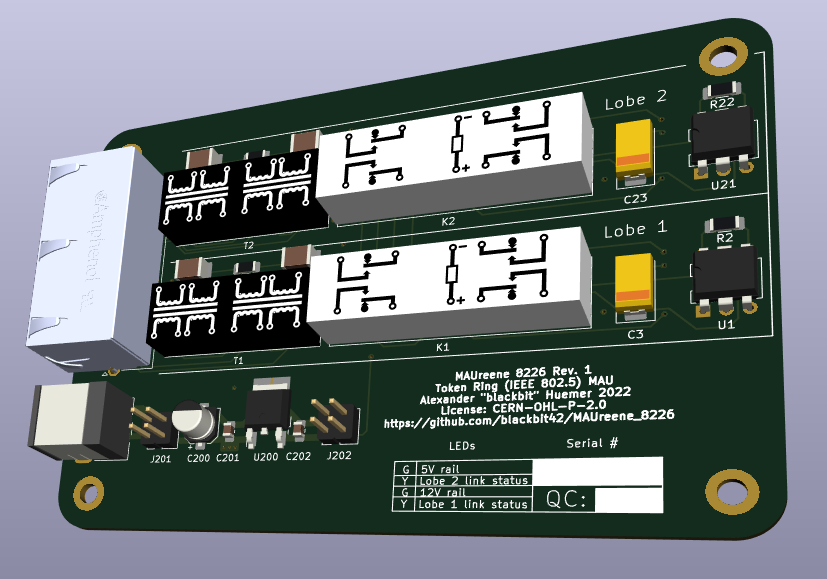
Kicad:
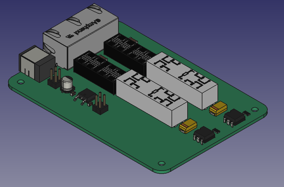
FreeCAD:
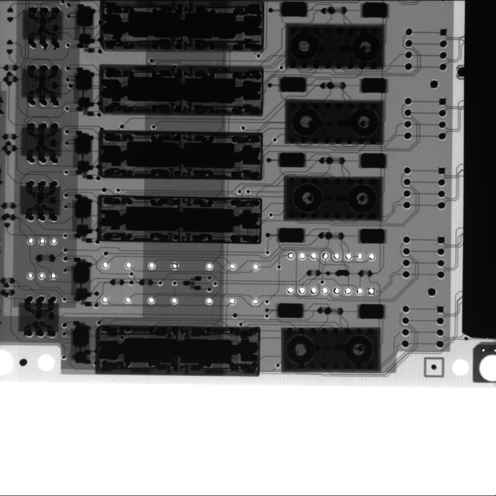
X-ray of original PCB, courtesy of @Manawyrm:
https://www.ieee802.org/5/www8025org/
https://ardent-tool.com/network/Understanding_Token_Ring.html
| Qty | Value | Footprint | References |
|---|---|---|---|
| 8 | 0R | Resistor_SMD:R_0603_1608Metric_Pad0.98x0.95mm_HandSolder | R3, R4, R12, R13, R23, R24, R32, R33 |
| 6 | R | Resistor_SMD:R_0603_1608Metric_Pad0.98x0.95mm_HandSolder | R7, R11, R27, R31, R200, R201 |
| 4 | 100 | Resistor_SMD:R_0603_1608Metric_Pad0.98x0.95mm_HandSolder | R5, R6, R25, R26 |
| 4 | 120n | Capacitor_SMD:C_0603_1608Metric_Pad1.08x0.95mm_HandSolder | C4, C5, C24, C25 |
| 4 | 330n | Capacitor_SMD:C_1812_4532Metric_Pad1.57x3.40mm_HandSolder | C1, C2, C21, C22 |
| 4 | MountingHole | MountingHole:MountingHole_3.2mm_M3_DIN965_Pad | H1, H2, H3, H4 |
| 4 | Q_NPN_BEC | Package_TO_SOT_SMD:SOT-23 | Q1, Q2, Q21, Q22 |
| 2 | 100n | Capacitor_SMD:C_0805_2012Metric_Pad1.18x1.45mm_HandSolder | C201, C202 |
| 2 | 10k | Resistor_SMD:R_0603_1608Metric_Pad0.98x0.95mm_HandSolder | R8, R28 |
| 2 | 22u | Capacitor_Tantalum_SMD:CP_EIA-7343-31_Kemet-D_Pad2.25x2.55mm_HandSolder | C3, C23 |
| 2 | 2k | Resistor_SMD:R_0603_1608Metric_Pad0.98x0.95mm_HandSolder | R9, R29 |
| 2 | 3.7k | Resistor_SMD:R_0805_2012Metric_Pad1.20x1.40mm_HandSolder | R10, R30 |
| 2 | 4.8k | Resistor_SMD:R_1206_3216Metric_Pad1.30x1.75mm_HandSolder | R1, R21 |
| 2 | 4PDT_relay | Token_Ring_MAU:4PDT_Relay | K1, K2 |
| 2 | D | Diode_SMD:D_SOD-123F | D1, D21 |
| 2 | H11A1 | Package_DIP:DIP-6_W7.62mm | U1, U21 |
| 2 | R | Resistor_SMD:R_1206_3216Metric_Pad1.30x1.75mm_HandSolder | R2, R22 |
| 2 | Transformer_Token_Ring_1to1_1to1 | Token_Ring_MAU:Pulse PE-64974 | T1, T2 |
| 1 | 0.33u | Capacitor_SMD:CP_Elec_5x5.8 | C200 |
| 1 | 12V Jumper | Connector_PinHeader_2.54mm:PinHeader_2x02_P2.54mm_Vertical | J201 |
| 1 | 5V Jumper | Connector_PinHeader_2.54mm:PinHeader_2x02_P2.54mm_Vertical | J202 |
| 1 | Barrel_Jack | Token_Ring_MAU:BarrelJack_CUI_PJ-063AH_Horizontal | J200 |
| 1 | KA78M05_TO252 | Package_TO_SOT_SMD:TO-252-2 | U200 |
| 1 | RJ45_LED_Shielded_x2 | Token_Ring_MAU:RJ45_Amphenol_RJHSE538X-02 | J1 |

dojoe/Twonkie
A USB-PD sniffer/injector/sink based on Google's Twinkie, re-designed to be manufactured by mere mortals.


themainframe/5g-m2-usb3-interface-pcb
KiCad EDA Project for my 5G M.2 (NGFF) USB3 Interface board

It measures 100 × 70 mm and has 4 copper layers, 1.61 mm thick.
62 parts, built around the H11A1. The full list of its parts is on this page, with links to each part's symbol and footprint where PCBKit's library has them.
From the blackbit42/MAUreene_8226 repository on GitHub, at the commit this page was made from: the board is Token_Ring_MAU.kicad_pcb and its schematic Token_Ring_MAU.kicad_sch. PCBKit opens the board in the browser, with nothing to install.
Its repository publishes it under the CERN-OHL-P-2.0 licence: you may reuse it on that licence's terms (keep the author's notice, and for a copyleft licence share your changes alike).