2 layers140.5 × 30 mm
Type e
google/mozc-devices
Circuit diagrams and firmware source code for Gboard DIY keyboards
16 parts3kApache-2.0

 bjpirt/shutter-tester100
An easy-to-build three point camera shutter speed tester
Shutter tester is an open-source printed circuit board by bjpirt, from the bjpirt/shutter-tester repository on GitHub. It is a 2-layer board of 50 × 34 mm with 16 parts on 19 nets, routed with 63 tracks and 0 vias.
Its parts include 9 resistors, 4 ICs and 3 capacitors. It belongs with the ESP32 and RISC-V boards of this library.
A low cost but capable three-point shutter speed tester that runs on ESP32. It uses the PCB design to provide the physical structure of the tester so that all you need to do is solder it together and all of the mechanical design is taken care of. It runs on ESP32 so is easily updated using the Arduino platform. The project is 100% open source (see the license file for details). The UI runs in the browser and communicates with the shutter tester via Bluetooth - you can try out the UI here.
The design of the shutter tester is quite simple; it uses three IS485E / IS486E light sensors with built-in amplifiers to trigger three digital input interrupts on the ESP32 MCU. I wanted to keep the front side of the PCB clear to avoid it ever scratching the camera body so have opted for using surface mount components. I've used quite large packages for these so that they can be more easily hand soldered. The ESP32 uses an "ESP32 C3 Super Mini" module which is very small, can be surface mounted and has USB C built-in which can be used to power the whole board. I've kept the PCB size down to 50mm so that you can take advantage of low cost PCB fabrication. There are silk-screen markings to help position the tester over the camera shutter and three large holes to help see the edges from behind. It should either be taped in place or held with an elastic band.
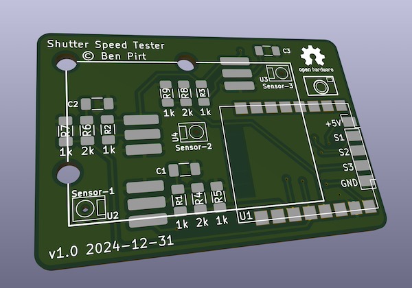
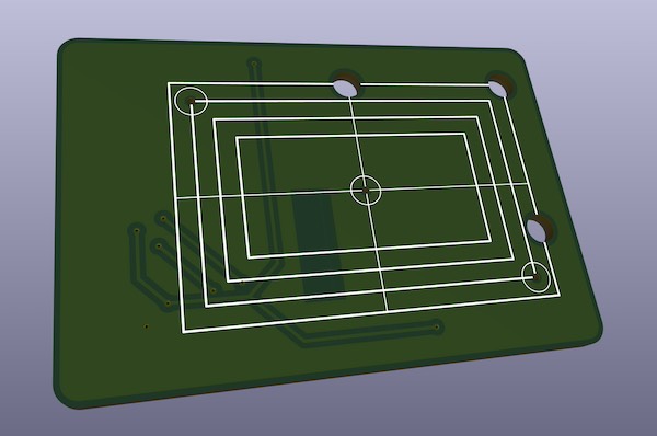
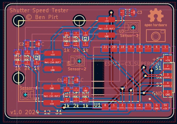
The sensor has a Bluetooth connection and you can connect this to Chrome to use quite a capable web interface so you can get a lot of detail on the calibration. You can try out the UI here
The BoM is quite low cost and relatively minimal:
The main thing to take care over during assembly is to ensure the lens of the light sensor aligns to the small hole in the PCB that allows the light through. The three legs of the sensor should be bent down slightly so that they can solder onto the three pads on the PCB.
The capacitors and resistors can be easily hand soldered (a finer soldering iron tip helps here) by applying solder to one of the pads on the PCB, using tweezers, solder one end of the component to the soldered pad on the PCB, then solder the other end once it is held in place. If you're experienced in surface mounting you could always use solder paste, but it's pretty straightforward without this. There are markings on the board for which component goes where (C1, C2 and C3 for the capacitors, Resistor values are marked 1k and 2k). The capacitors are optional and may be removed in a future iteration.
It's best to test the ESP32 module before soldering to ensure it's working fine. Program this using the sketch included and make sure it is outputting "Ready to measure" on the serial console (running at 921600 baud).
It's a good idea to place some black insulation tape over the back of the sensors otherwise stray light can cause false readings.
Attach the shutter tester behind the shutter of the camera (I normally use 2 - 3 small blobs of Blu-Tak which works well). You can use the three larger holes in the tester to align with the edges of the shutter aperture. Open the shutter once you've this so you can check it's properly positioned by setting the shutter to "Bulb" and opening it. Remove the lens (if possible) and place a strong, even light at the front of the camera. You can use a full size bulb for this so long as it is the type that has a white diffuser bulb, not clear. Basically you want to ensure that light can pass directly through the three holes to reach the sensors, not at an angle. I've also had good results with a small USB powered LED panel.
There is a user interface that connects to the ESP32 from a Chrome web browser directly and lets you analyse all of the measurements quite easily.
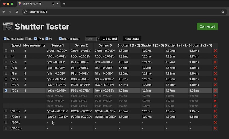
You can easily use the latest version. You should then be able to click the Connect button and pair with your shutter tester using Bluetooth. Select the speed you want to test, set up the light and fire the shutter. The new reading should appear in the table.
If you want to just try out the UI without a tester, you can use this link and the "Test" button will simulate a shutter being fired. From a privacy perspective, the UI runs entirely in your browser and nothing goes over the internet.
If you want to run this locally you can do the following:
ui folder of this repositorynpm installnpm run devOpen a serial terminal to the ESP32 (this is built in to the Arduino IDE). You'll need to connect at 921600 baud.
Fire the shutter and it will print out the timings to the serial console. There are two sets of timings:
Ready to measure

Shutter timing
Shutter 1: 1-2: 16582 uS || 2-3: 12632 uS
Shutter 2: 1-2: 23756 uS || 2-3: 18462 uS

Exposure timing
Sensor 1: 4346 uS || 4.3 mS || 1 / 228
Sensor 2: 5028 uS || 5.0 mS || 1 / 198
Sensor 3: 5528 uS || 5.5 mS || 1 / 182
In this example, the time taken for the first shutter to travel between the first and second (centre) sensors was 16582 microseconds and 12632 microseconds between the second (centre) and third sensor. You can see that in this example the second shutter is slow and would need adjusting.
Looking at the exposure time at each sensor, you can see the timings would need adjusting to give a good even exposure. First you would adjust the shutter timings to try and get them similar and then adjust both shutter tensioners to get the exposure time to match the expected (in this case it should have been 1/250 S)
| Qty | Value | Footprint | References |
|---|---|---|---|
| 6 | 1k | Resistor_SMD:R_1206_3216Metric_Pad1.30x1.75mm_HandSolder | R1, R2, R3, R4, R6, R8 |
| 3 | 0.01uF | Capacitor_SMD:C_1206_3216Metric_Pad1.33x1.80mm_HandSolder | C1, C2, C3 |
| 3 | 2k | Resistor_SMD:R_1206_3216Metric_Pad1.30x1.75mm_HandSolder | R5, R7, R9 |
| 1 | ESP32-C3_SUPERMINI | ESP32-C3_SUPERMINI:MODULE_ESP32-C3_SUPERMINI_SMT | U1 |
| 1 | Sensor-1 | OptoDevice:Sharp_IS485_Flat_Mount | U2 |
| 1 | Sensor-2 | OptoDevice:Sharp_IS485_Flat_Mount | U4 |
| 1 | Sensor-3 | OptoDevice:Sharp_IS485_Flat_Mount | U3 |
google/mozc-devices
Circuit diagrams and firmware source code for Gboard DIY keyboards

conorpp/u2f-zero
U2F USB token optimized for physical security, affordability, and style

rusefi/rusefi
rusefi - GPL internal combustion engine control unit

VoronDesign/Voron-Hardware
Cool Hardware designed by the Voron Design group

hoglet67/RGBtoHDMI
Bare-metal Raspberry Pi project that provides pixel-perfect sampling of Retro Computer RGB/YUV video and conversion to HDMI

hackclub/OnBoard
💡 Join 1,000 teenagers and make your first PCB with a $100 grant!


It measures 50 × 34 mm and has 2 copper layers, 1.6 mm thick.
16 parts. The full list of its parts is on this page, with links to each part's symbol and footprint where PCBKit's library has them.
From the bjpirt/shutter-tester repository on GitHub, at the commit this page was made from: the board is hardware/shutter-tester.kicad_pcb and its schematic hardware/shutter-tester.kicad_sch. PCBKit opens the board in the browser, with nothing to install.
Its repository states no licence, so its author keeps all rights: ask bjpirt before reusing the design.