
4 layers37 × 34.3 mm
Readout 60pin
opentac/opentac
OpenTac: open tools to design, fabricate, read and simulate flex-PCB tactile skins that sense normal and shear force, for any robot surface.
55 parts92MIT

 bitbangbill/simple-bipolar-supply
A small reliable +/- 5V power supply designed for project integration. The supply itself sits on a board with castellated edges making it ideal for board mounting.
Simple bipolar suppy is an open-source printed circuit board by bitbangbill, from the bitbangbill/simple-bipolar-supply repository on GitHub, published under the GPL-3.0 licence. It is a 2-layer board of 25.4 × 25.4 mm with 22 parts on 11 nets, routed with 62 tracks and 20 vias.
It is built around the LM2776DBV. Its parts include 10 capacitors, 4 resistors, 2 ICs, 2 diodes and 2 inductors. It belongs with the power boards of this library.
The simple bipolar supply is a USB-C powered dual channel (positive and negative) power supply. The module is a drop in system for projects requiring a bipolar suppy. The project is designed to be a series of building blocks a tailored supply for any application.
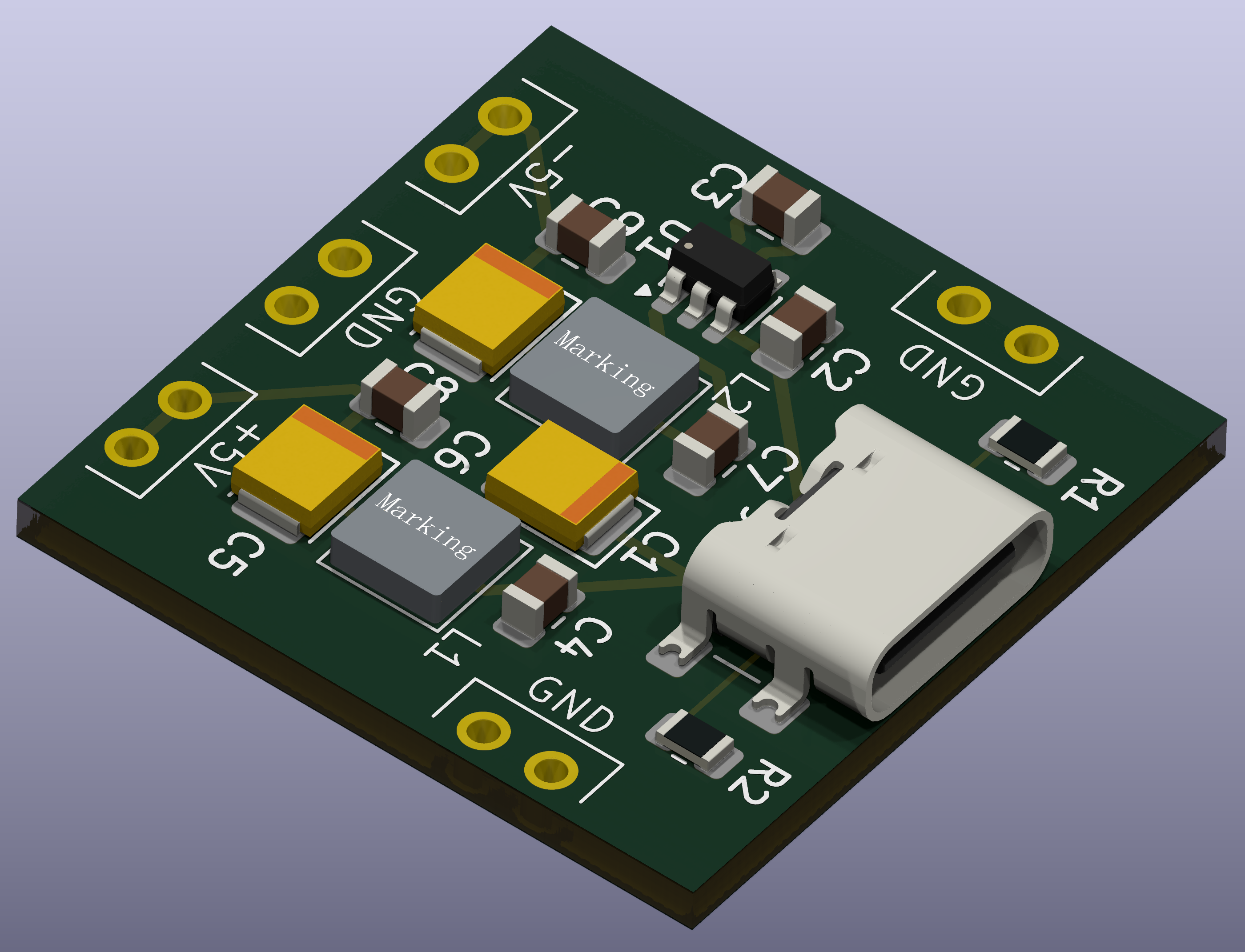 Revision B of the charge-pump variant rendered in KiCad
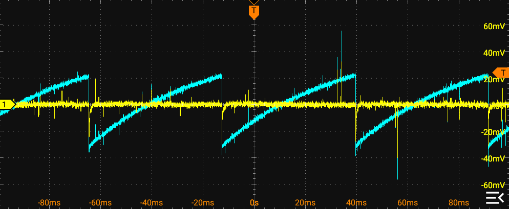 Charge pump output noise (blue) compared to +5V output (yellow). Notice the transient on the +5V output everytime the converter switches.
The long term plan is to develop multiple building blocks for two primary variants of the power supply. The building blocks and whole system are outlined in the system block diagram. Only the first two blocks are implemented in the first revision. Each block in the diagram between USB-C and output can be added and removed as necesary.
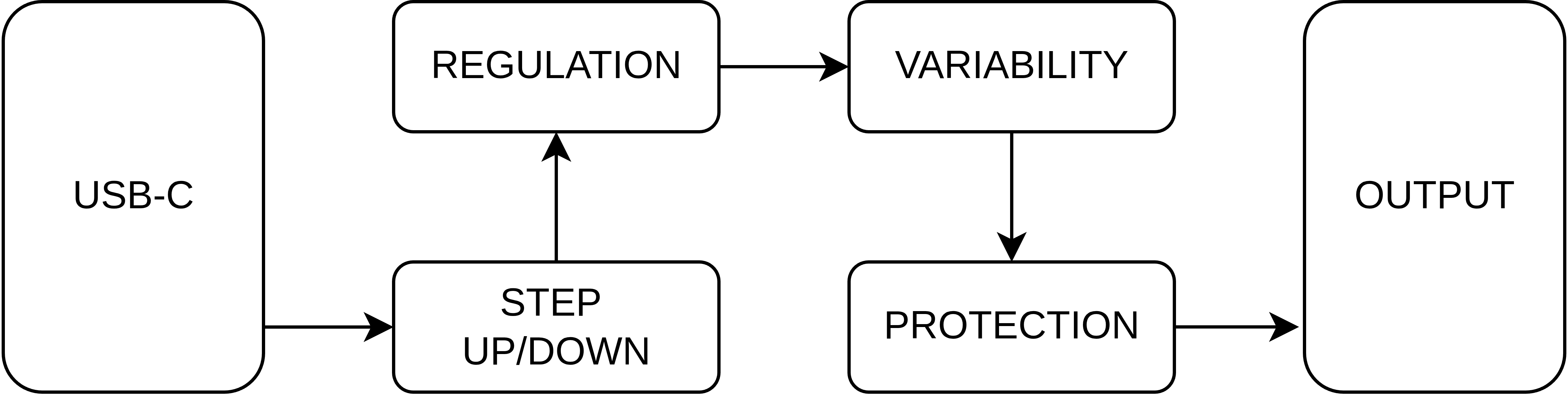 Block diagram convering the project roadmap
| Qty | Value | Footprint | References |
|---|---|---|---|
| 3 | 100n | Capacitor_SMD:C_0805_2012Metric | C3, C7, C10 |
| 3 | 10u | Capacitor_Tantalum_SMD:CP_EIA-3528-12_Kemet-T | C1, C6, C9 |
| 2 | 0.82u | small-bipolar-supply:SRP4020 | L1, L2 |
| 2 | 100 | Resistor_SMD:R_0805_2012Metric | R3, R4 |
| 2 | 2.2u | Capacitor_SMD:C_0805_2012Metric | C5, C8 |
| 2 | 5.1k | Resistor_SMD:R_0805_2012Metric | R1, R2 |
| 1 | 1u | Capacitor_SMD:C_0805_2012Metric | C4 |
| 1 | 4.7u | Capacitor_SMD:C_0805_2012Metric | C2 |
| 1 | BLUE | LED_SMD:LED_0805_2012Metric | D3 |
| 1 | GREEN | LED_SMD:LED_0805_2012Metric | D1 |
| 1 | LM2776 | Package_TO_SOT_SMD:SOT-23-6 | U1 |
| 1 | LOGO | small-bipolar-supply:polar | G*** |
| 1 | USB_C_Receptacle_PowerOnly_6P | Connector_USB:USB_C_Receptacle_GCT_USB4135-GF-A_6P_TopMnt_Horizontal | J1 |
| 1 | module_connectors | small-bipolar-supply:module-footprint | U2 |
opentac/opentac
OpenTac: open tools to design, fabricate, read and simulate flex-PCB tactile skins that sense normal and shear force, for any robot surface.


lengoctuong2005/KiCad-PCB-Labs
Tập hợp toàn bộ các bài thực hành và đồ án thiết kế PCB (KiCad) trong khóa học Thiết kế Mạch In / Vi Mạch.


ajisrawi/sentinel-uhf-radar
Reference design of a two-face UHF early-warning phased-array radar: system sizing, MoM antenna simulation, seven KiCad PCB projects, Blender site model

andymartell/Prius-STM32-DC-Motor-Contoller
STM32 based DC Motor Controller using Prius Gen 3 hardware
It measures 25.4 × 25.4 mm and has 2 copper layers, 1.6 mm thick.
22 parts, built around the LM2776DBV. The full list of its parts is on this page, with links to each part's symbol and footprint where PCBKit's library has them.
From the bitbangbill/simple-bipolar-supply repository on GitHub, at the commit this page was made from: the board is electrical/simple-bipolar-suppy.kicad_pcb and its schematic electrical/simple-bipolar-suppy.kicad_sch. PCBKit opens the board in the browser, with nothing to install.
Its repository publishes it under the GPL-3.0 licence: you may reuse it on that licence's terms (keep the author's notice, and for a copyleft licence share your changes alike).