
4 layers110 × 40.7 mm
Drone V2 Remote
hackclub/OnBoard
💡 Join 1,000 teenagers and make your first PCB with a $100 grant!
49 parts915
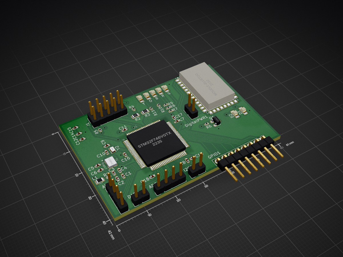
This board includes a HC-05 Bluetooth module which exposes a serial port interface over bluetooth as a direct link with the microcontroller.
Digital is an open-source printed circuit board by BiomedicalCircuits, from the BiomedicalCircuits/STM32_HC05 repository on GitHub. It is a 4-layer board of 61 × 42 mm with 49 parts on 124 nets, routed with 324 tracks and 34 vias.
Its parts include 18 capacitors, 11 resistors, 2 ICs, 2 crystals and 1 transistor. It belongs with the STM32 boards of this library.
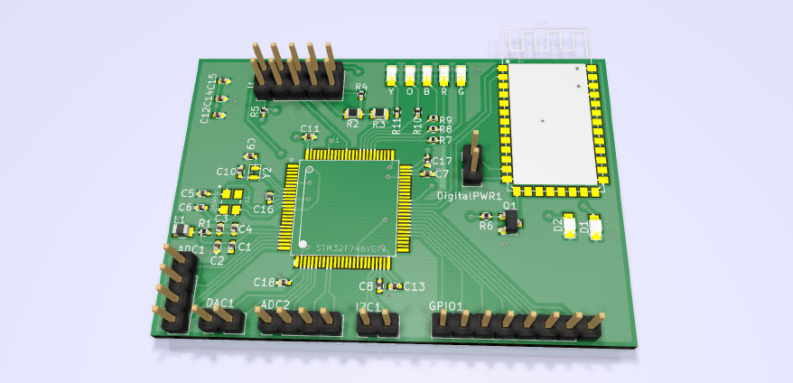
This is a PCB board designed in KiCAD which implements a STM32F746VGT6 microcontroller exposing the following pins and internal connections. All of the GPIO pins support timer peripheral output, for a more detailed view of the potential PIN function, check the STM32F7 datasheet using name as a reference. Please read STM32F7 Reference page and Getting Started Guide.
This board includes a HC-05 Bluetooth module which exposes a serial port interface over bluetooth as a direct link with the microcontroller. The bluetooth module is switched on/off with a transistor switch controlled by a microcontroller pin.
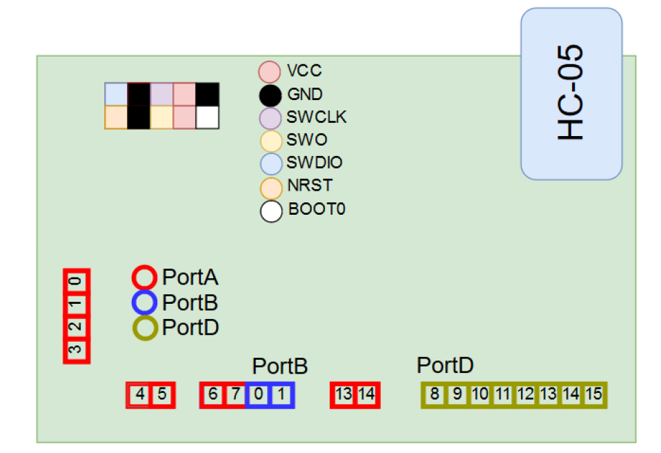
| Name | Pin | Extra Functions |
|---|---|---|
| PA0 | 22 | ADC0, UART4_TX, USART2_CTS |
| PA1 | 23 | ADC1, UART4_RX, USART2_RTS |
| PA2 | 24 | ADC2, USART2_TX |
| PA3 | 25 | ADC3, USART2_RX |
| PA4 | 28 | ADC4, USART2_CLK |
| PA5 | 29 | ADC5, SPI1_CLK |
| PA6 | 30 | ADC6, SPI1_MISO |
| PA7 | 31 | ADC7, SPI1_MOSI |
| PB0 | 34 | ADC8 |
| PB1 | 35 | ADC9 |
| PB10 | 46 | I2C2_CLK |
| PB11 | 47 | I2C2_SDA |
| PD8 | 55 | USART3_TX |
| PD9 | 56 | USART3_RX |
| PD10 | 57 | USART3_CLK |
| PD11 | 58 | USART3_CTS |
| PD12 | 59 | USART3_RTS |
| PD13 | 60 | |
| PD14 | 61 | |
| PD15 | 62 | |
| PD0 | 81 | Green LED |
| PD1 | 82 | Red LED |
| PD2 | 83 | Blue LED |
| PD3 | 84 | Orange LED |
| PD4 | 85 | Yellow LED |
| PC6 | 63 | HC-05 UART RX |
| PC7 | 64 | HC-05 UART TX |
| PC8 | 65 | HC-05 BT KEY |
| PE12 | 42 | Bluetooth Enable |
The programming and power port is located on the upper left section of the board. The flashing debugging must be performed using a ST-Link/v2 debugger or STM32FX evaluation board (Discovery, Nucleo, etc ...). LEDs are connected to GPIO (PD0-4), bluetooth module is connected to UART6 port and the bluetooth module on/off actuation is driven by GPIO PE12. Further information on programming and the specific pin functions can be found on the STM32F7 datasheet, and the HC-05 bluetooth module reference guide.
The following 4 files form the required interface to program and operate the Bluetooth module via the UART peripheral of the STM32F7.
#ifndef __bluetooth_H
#define __bluetooth_H
#ifdef __cplusplus
 extern "C" {
#endif

/* Includes ------------------------------------------------------------------*/
#include "stm32f7xx_hal.h"
#include "stdlib.h"
#include <stdio.h>
#include <string.h>
#include "gpio.h"

void BT_isAlive(void);
void BT_setNameMixcell(void);
void BT_clearPaired(void);
void BT_setMaster(void);
void BT_setSlave(void);
void BT_setCOM(void);
void BT_Reset(void);
void BT_Restore(void);
void BT_SendTest(void);
void BT_CMode(void);
void BT_Init_UART(void);#include "bluetooth.h"
extern UART_HandleTypeDef UART;
extern char data_rx[32];
extern char rx_data[8]; /* Buffer used for UART */
void BT_isAlive(void)
{
char data_tx[4] = "AT\r\n";
memset(data_rx, 0x00, 32);
HAL_UART_Transmit(&UART, (uint8_t *) data_tx, 4, 1000);
HAL_UART_Receive(&UART, (uint8_t *) data_rx, 24, 1000);
}
void BT_setName(void)
{
// TODO Set Bluetooth name: MY_NAME.
char data_tx[17] = "AT+NAME=MY_NAME\r\n";
memset(data_rx, 0x00, 32);
HAL_UART_Transmit(&UART, (uint8_t *) data_tx, 17, 500);
HAL_UART_Receive(&UART, (uint8_t *) data_rx, 24, 500);
}
/**
  ******************************************************************************
  * File Name          : UART.h
  * Date               : 13/04/2015 14:34:07
  * Description        : This file provides code for the configuration
  *                      of the USART instances.
  ******************************************************************************
  *
  * COPYRIGHT(c) 2015 STMicroelectronics
  *
  * Redistribution and use in source and binary forms, with or without modification,
  * are permitted provided that the following conditions are met:
  *   1. Redistributions of source code must retain the above copyright notice,
  *      this list of conditions and the following disclaimer.
  *   2. Redistributions in binary form must reproduce the above copyright notice,
  *      this list of conditions and the following disclaimer in the documentation
  *      and/or other materials provided with the distribution.
  *   3. Neither the name of STMicroelectronics nor the names of its contributors
  *      may be used to endorse or promote products derived from this software
  *      without specific prior written permission.
  *
  * THIS SOFTWARE IS PROVIDED BY THE COPYRIGHT HOLDERS AND CONTRIBUTORS "AS IS"
  * AND ANY EXPRESS OR IMPLIED WARRANTIES, INCLUDING, BUT NOT LIMITED TO, THE
* IMPLIED WARRANTIES OF MERCHANTABILITY AND FITNESS FOR A PARTICULAR PURPOSE ARE#include "usart.h"
#include "gpio.h"
#include <stdio.h>
#include <math.h>
#include "stdlib.h"
#include <string.h>
UART_HandleTypeDef UART;
char data_rx[32] = "";
extern char rx_data[8]; /* Buffer used for UART */
extern uint16_t INFO_TO_SEND[1024]; /* Buffer used for ADC */
/* USART6 init function */
void MX_USART_UART_Init(void)
{
UART.Instance = USART6;
UART.Init.BaudRate = 38400;
UART.Init.WordLength = UART_WORDLENGTH_8B;
UART.Init.StopBits = UART_STOPBITS_1;
UART.Init.Parity = UART_PARITY_NONE;
UART.Init.Mode = UART_MODE_TX_RX;
UART.Init.HwFlowCtl = UART_HWCONTROL_NONE;
UART.Init.OverSampling = UART_OVERSAMPLING_16;| Qty | Value | Footprint | References |
|---|---|---|---|
| 10 | 100nF | Capacitors_SMD:C_0402 | C2, C4, C11, C12, C13, C14, C15, C16, C17, C18 |
| 7 | LED | LEDs:LED_0805 | B, D1, D2, G, O, R, Y |
| 6 | 47 | Resistors_SMD:R_0402 | R1, R7, R8, R9, R10, R11 |
| 3 | 33K | Resistors_SMD:R_0402 | R4, R5, R6 |
| 3 | Conn_01x02 | Pin_Headers:Pin_Header_Straight_1x02_Pitch2.54mm | DAC1, DigitalPWR1, I2C1 |
| 2 | 1uF | Capacitors_SMD:C_0402 | C1, C3 |
| 2 | 2.2uF | Capacitors_SMD:C_0402 | C7, C8 |
| 2 | 22nF | Capacitors_SMD:C_0402 | C5, C6 |
| 2 | 33K | Resistors_SMD:R_0805 | R2, R3 |
| 2 | 6pF | Capacitors_SMD:C_0402 | C9, C10 |
| 2 | Conn_01x04 | Pin_Headers:Pin_Header_Straight_1x04_Pitch2.54mm | ADC1, ADC2 |
| 1 | 25MHz | User_library:OSCCC320X250X60N | Y1 |
| 1 | 32kHz | Crystals:Crystal_SMD_2012-2pin_2.0x1.2mm | Y2 |
| 1 | Conn_01x08 | Pin_Headers:Pin_Header_Straight_1x08_Pitch2.54mm | GPIO1 |
| 1 | Conn_02x05_Odd_Even_MountingPin | Pin_Headers:Pin_Header_Straight_2x05_Pitch2.54mm | J1 |
| 1 | INDUCTOR | Inductors_SMD:L_0805 | L1 |
| 1 | MOUDLE-BLUETOOTH-HC-05(34P-27X13MM) | myKiCADLibrary:HC05 | U2 |
| 1 | Q_NMOS_GSD | TO_SOT_Packages_SMD:SOT-23 | Q1 |
| 1 | STM32F746VGTx | myKiCADLibrary:LQFP100 | U1 |
hackclub/OnBoard
💡 Join 1,000 teenagers and make your first PCB with a $100 grant!


AndreiVladescu/ESP32-Bit-Pirate-Hardware
Carrier breaker-board for the ESP32-S3 Devkit. Works great with the ESP32-Bit-Pirate firmware.


h0lad/SolarMeshtasticNode
This is a Meshtastic Solar Node PCB based on the Heltec HT-CT62 and the linear solar charge controller TI BQ25185.
It measures 61 × 42 mm and has 4 copper layers, 1.6 mm thick.
49 parts. The full list of its parts is on this page, with links to each part's symbol and footprint where PCBKit's library has them.
From the BiomedicalCircuits/STM32_HC05 repository on GitHub, at the commit this page was made from: the board is Digital.kicad_pcb. PCBKit opens the board in the browser, with nothing to install.
Its repository states no licence, so its author keeps all rights: ask BiomedicalCircuits before reusing the design.