2 layers74.9 × 26.8 mm
 BinaryS010/ossw8
Open SCART Switch
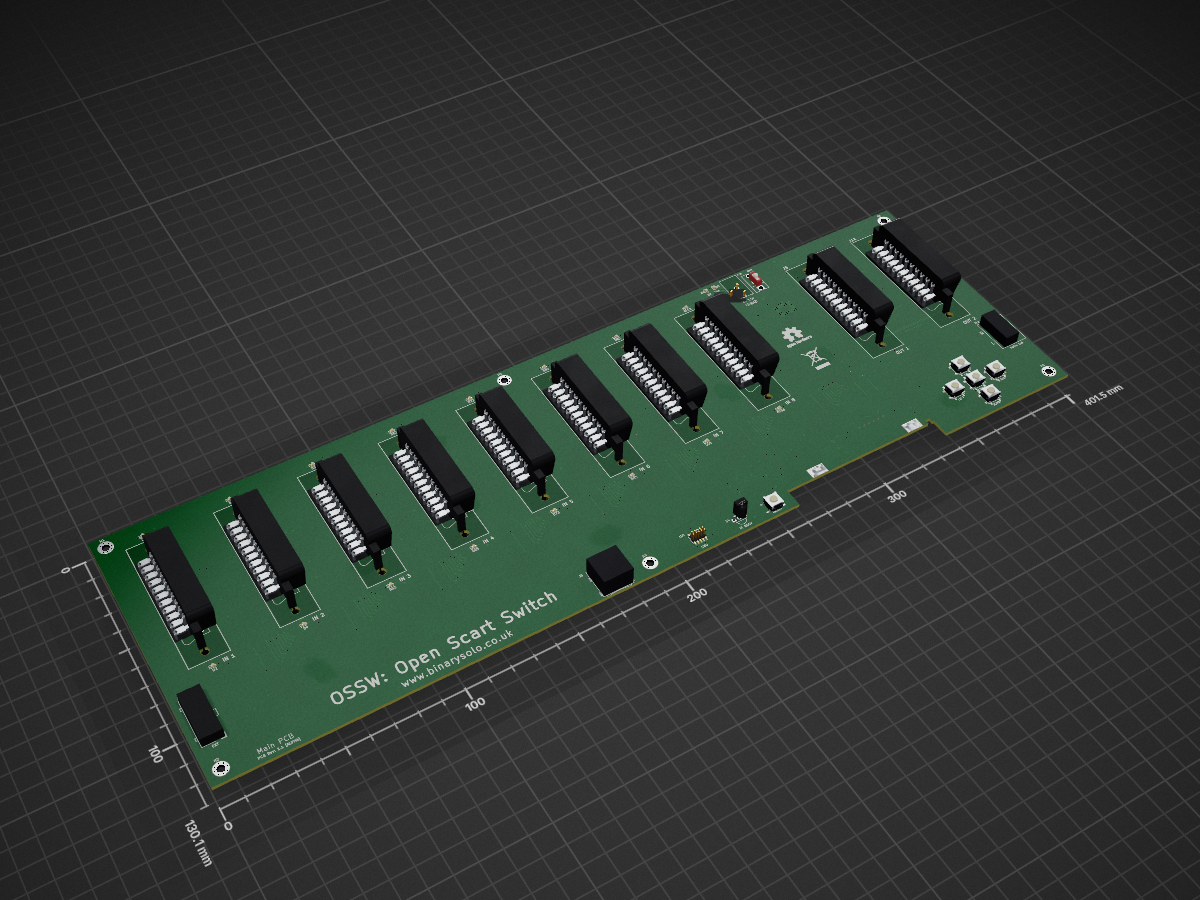
Ossw is an open-source printed circuit board by BinaryS010, from the BinaryS010/ossw repository on GitHub, published under the GPL-3.0 licence. It is a 4-layer board of 401.5 × 130.1 mm with 336 parts on 303 nets, routed with 3,043 tracks and 574 vias.
It is built around the LM1881, SN74CBT3244DW and TS5A3159DCK, with the 24LC64(LX), 74HC14 and BSS138 among its other parts. Its parts include 101 diodes, 88 resistors, 60 capacitors, 17 ICs and 16 connectors. It belongs with the SAM D and SAM boards of this library.


The Open SCART Switch (OSSW) is an RGB video and audio SCART switch designed to connect up to 8 RGB capable video game consoles with compatible display devices or scalers such as the Open Source Scan Converter (OSSC).
It was designed for use with properly constructed RGB SCART cables which correctly attenuate video and sync signals to levels safe for use with consumer grade televisions and the OSSC.
I designed this device to scratch a few itches, but mostly because there are currently no open source SCART switch designs within the retro gaming community.
It would have been cheaper to buy an existing solution, of which there are several very good ones, but I've learnt a lot throughout this project.
Currently the OSSW has the following features:
The following are known limitations with the OSSW:
The following features are planned for the OSSW:
Currently the device should only be used with 75 ohm attenuated sync signals. Using the OSSW with TTL level sync signals will likely damage upstream devices such as the OSSC.
OSSW hardware overview and build instructions are located in the HARDWARE readme.
OSSW firmware build, programming and debugging instructions are located in the FIRMWARE readme.
OSSW usage instructions are located in the USAGE readme.
Please see the CHANGELOG
This is a DIY hobby project currently in an early prototype stage.
I am not a trained electrical engineer and although this device seems to work well with my equipment it may not work so well with other setups.
I do not intend to sell kits or completed devices. Design files are released to the community in the hope that the design may be improved upon should people wish to contribute.
I may sell surplus PCBs at around cost price (+shipping) but ONLY if I have them available.
I offer NO WARRANTY of any kind and assume NO RESPONSIBILITY for potential damage or loss caused by this device. Use the information in the repository at your own risk.
I also offer NO GUARANTEE of support if you attempt to build and operate one of these devices. This is a hobby project and not a business. I'm open to contributions and suggestions on current or future features but it's unlikely I'll have time to answer direct queries.
Donations are certainly not expected or required. However, if you would like to contribute a small donation towards future revisions of this project then please use one of the methods below:
Any and all donations are greatly appreciated.
This project is licensed under the GNU General Public License, version 3 (GPLv3).
The Open Scart Switch (OSSW) project is Copyright(c) 2019-2021 Binary Solo.
Elements of the OSSW project that are derived from other works are credited within the relevant source files. Those works are copyright of their respective owners as indicated in the original copyright notice.
The OSSW developer can be contacted via email as ossw AT binarysolo.co.uk (replace the AT with @).
| Qty | Value | Footprint | References |
|---|---|---|---|
| 80 | D_TVS | Diode_SMD:D_0402_1005Metric | D10, D11, D12, D13, D14, D15, D16, D17, D18, D19, D20, D21, D22, D23, D100, D101 +64 |
| 37 | 10K | Resistor_SMD:R_0603_1608Metric | R11, R12, R13, R14, R19, R20, R21, R22, R23, R24, R25, R26, R27, R28, R31, R33 +21 |
| 34 | 0.1uF | Capacitor_SMD:C_0603_1608Metric | C1, C2, C10, C12, C13, C15, C16, C17, C18, C19, C20, C26, C31, C40, C41, C42 +18 |
| 16 | 220R | Resistor_SMD:R_0603_1608Metric | R1, R2, R3, R4, R60, R61, R62, R63, R64, R65, R66, R67, R68, R69, R70, R71 |
| 16 | LED_Small | LED_SMD:LED_0603_1608Metric | D1, D2, D3, D4, D52, D53, D62, D63, D72, D73, D82, D83, D92, D93, D102, D103 |
| 14 | 75R | Resistor_SMD:R_0603_1608Metric | R32, R34, R35, R36, R37, R42, R43, R44, R45, R46, R47, R48, R49, R73 |
| 10 | BSS138 | Package_TO_SOT_SMD:SOT-23 | Q3, Q4, Q5, Q7, Q8, Q9, Q10, Q11, Q12, Q13 |
| 8 | 220uF | Capacitor_SMD:CP_Elec_6.3x7.7 | C32, C33, C34, C35, C36, C37, C38, C39 |
| 8 | SN74CBT3244 | Package_SO:SOIC-20W_7.5x12.8mm_P1.27mm | U1, U2, U10, U11, U12, U13, U14, U15 |
| 6 | 100nF | Capacitor_SMD:C_0603_1608Metric | C27, C28, C29, C30, C54, C55 |
| 6 | MountingHole | MountingHole:MountingHole_3.2mm_M3_Pad_Via | H1, H2, H3, H4, H5, H6 |
| 5 | 2K2 | Resistor_SMD:R_0603_1608Metric | R15, R79, R80, R81, R82 |
| 5 | 5.6M | Resistor_SMD:R_0603_1608Metric | R38, R39, R40, R41, R74 |
| 4 | 10uF | Capacitor_SMD:CP_Elec_4x5.4 | C5, C21, C23, C25 |
| 3 | 1K | Resistor_SMD:R_0603_1608Metric | R9, R10, R17 |
| 2 | 10uF | Capacitor_SMD:C_0603_1608Metric | C6, C60 |
| 2 | 1N4002 | Diode_SMD:D_SMA | D5, D7 |
| 2 | 4K7 | Resistor_SMD:R_0603_1608Metric | R5, R6 |
| 2 | 6.4pF | Capacitor_SMD:C_0603_1608Metric | C3, C4 |
| 2 | TS5A3159DCK | Package_TO_SOT_SMD:SOT-363_SC-70-6 | U16, U18 |
| 1 | 100pF | Capacitor_SMD:C_0603_1608Metric | C14 |
| 1 | 10V | Diode_SMD:D_SOD-123 | D6 |
| 1 | 12K | Resistor_SMD:R_0603_1608Metric | R29 |
| 1 | 150R | Resistor_SMD:R_0603_1608Metric | R30 |
| 1 | 15nF/50V | Capacitor_SMD:C_0603_1608Metric | C22 |
| 1 | 1A | Fuse:Fuse_1206_3216Metric | F1 |
| 1 | 1uF | Capacitor_SMD:C_0603_1608Metric | C11 |
| 1 | 24LC64 | Package_SO:MSOP-8_3x3mm_P0.65mm | U9 |
| 1 | 32.768kHz | Crystal:Crystal_SMD_MicroCrystal_CC8V-T1A-2Pin_2.0x1.2mm | Y1 |
| 1 | 330R | Resistor_SMD:R_0603_1608Metric | R16 |
| 1 | 39R | Resistor_SMD:R_0603_1608Metric | R18 |
| 1 | 3V3 | LED_SMD:LED_0603_1608Metric | D8 |
| 1 | 470R | Resistor_SMD:R_0603_1608Metric | R76 |
| 1 | 47uF | Capacitor_SMD:CP_Elec_6.3x5.4 | C24 |
| 1 | 5V | LED_SMD:LED_0603_1608Metric | D9 |
| 1 | 680K | Resistor_SMD:R_0603_1608Metric | R75 |
| 1 | 74HC14 | Package_SO:SOIC-14_3.9x8.7mm_P1.27mm | U5 |
| 1 | A1 | ossw:anchor | J16 |
| 1 | A2 | ossw:anchor | J17 |
| 1 | A3 | ossw:anchor | J18 |
| 1 | A4 | ossw:anchor | J19 |
| 1 | ACTION | ossw:LTL-613R-V-TR | SW4 |
| 1 | ATSAMD21J18A-AUT | Package_QFP:TQFP-64_10x10mm_P0.5mm | U3 |
| 1 | Audio Out | ossw:PSG01550 | J12 |
| 1 | BC847 | Package_TO_SOT_SMD:SOT-23 | Q1 |
| 1 | BC857 | Package_TO_SOT_SMD:SOT-23 | Q2 |
| 1 | BLANK1 | Jumper:SolderJumper-3_P1.3mm_Bridged12_RoundedPad1.0x1.5mm | JP2 |
| 1 | BLANK2 | Jumper:SolderJumper-3_P1.3mm_Bridged12_RoundedPad1.0x1.5mm | JP4 |
| 1 | BLANK3 | Jumper:SolderJumper-3_P1.3mm_Bridged12_RoundedPad1.0x1.5mm | JP6 |
| 1 | BLANK4 | Jumper:SolderJumper-3_P1.3mm_Bridged12_RoundedPad1.0x1.5mm | JP8 |
| 1 | BLANK5 | Jumper:SolderJumper-3_P1.3mm_Bridged12_RoundedPad1.0x1.5mm | JP10 |
| 1 | BLANK6 | Jumper:SolderJumper-3_P1.3mm_Bridged12_RoundedPad1.0x1.5mm | JP12 |
| 1 | BLANK7 | Jumper:SolderJumper-3_P1.3mm_Bridged12_RoundedPad1.0x1.5mm | JP14 |
| 1 | BLANK8 | Jumper:SolderJumper-3_P1.3mm_Bridged12_RoundedPad1.0x1.5mm | JP16 |
| 1 | BLM21PG331SN1 | Inductor_SMD:L_0603_1608Metric | FB1 |
| 1 | DC 7.5V | ossw:BarrelJack_FC681465P | J13 |
| 1 | DOWN | ossw:LTL-613R-V-TR | SW5 |
| 1 | EXT | ossw:TE_MATE-N-LOK_4-794630-4_2x07_P3.0mm_Vertical | J20 |
| 1 | FUNC1 | Jumper:SolderJumper-3_P1.3mm_Bridged12_RoundedPad1.0x1.5mm | JP1 |
| 1 | FUNC2 | Jumper:SolderJumper-3_P1.3mm_Bridged12_RoundedPad1.0x1.5mm | JP3 |
| 1 | FUNC3 | Jumper:SolderJumper-3_P1.3mm_Bridged12_RoundedPad1.0x1.5mm | JP5 |
| 1 | FUNC4 | Jumper:SolderJumper-3_P1.3mm_Bridged12_RoundedPad1.0x1.5mm | JP7 |
| 1 | FUNC5 | Jumper:SolderJumper-3_P1.3mm_Bridged12_RoundedPad1.0x1.5mm | JP9 |
| 1 | FUNC6 | Jumper:SolderJumper-3_P1.3mm_Bridged12_RoundedPad1.0x1.5mm | JP11 |
| 1 | FUNC7 | Jumper:SolderJumper-3_P1.3mm_Bridged12_RoundedPad1.0x1.5mm | JP13 |
| 1 | FUNC8 | Jumper:SolderJumper-3_P1.3mm_Bridged12_RoundedPad1.0x1.5mm | JP15 |
| 1 | IN 1 | ossw:SCART_Female | J1 |
| 1 | IN 2 | ossw:SCART_Female | J3 |
| 1 | IN 3 | ossw:SCART_Female | J2 |
| 1 | IN 4 | ossw:SCART_Female | J4 |
| 1 | IN 5 | ossw:SCART_Female | J7 |
| 1 | IN 6 | ossw:SCART_Female | J8 |
| 1 | IN 7 | ossw:SCART_Female | J9 |
| 1 | IN 8 | ossw:SCART_Female | J15 |
| 1 | IR RECV | OptoDevice:Vishay_MINICAST-3Pin | U4 |
| 1 | LCD | ossw:Socket_Strip_Angled_1x06_Pitch2.54mm | J11 |
| 1 | LEFT | ossw:LTL-613R-V-TR | SW3 |
| 1 | LM1881 | Package_SO:SOIC-8_3.9x4.9mm_P1.27mm | U17 |
| 1 | NCP1117ST33T3G | Package_TO_SOT_SMD:SOT-223 | U6 |
| 1 | NCP1117ST50T3G | Package_TO_SOT_SMD:SOT-223 | U8 |
The 322 most common of 336 parts.
It measures 401.5 × 130.1 mm and has 4 copper layers, 1.6 mm thick.
336 parts, built around the LM1881, SN74CBT3244DW, TS5A3159DCK and 24LC64(LX). The full list of its parts is on this page, with links to each part's symbol and footprint where PCBKit's library has them.
From the BinaryS010/ossw repository on GitHub, at the commit this page was made from: the board is pcb/main/prototype/rev-1.1/ossw.kicad_pcb. PCBKit opens the board in the browser, with nothing to install.
Its repository publishes it under the GPL-3.0 licence: you may reuse it on that licence's terms (keep the author's notice, and for a copyleft licence share your changes alike).

4rynv/Eklavya_Gantry
an attempt to automate screwing out and in of screw holes arranged in a matrix formation

wenzel-lab/droplet-sorter-master
Master repository that documents how the different parts come together of the open source hardware Fluorescence Activated (Microfluidic) Droplet Sorter (FADS).

ahessling/ActiveLoad
Small 12 Watt Active Load (dummy load) with STM32 microcontroller


dm2lct/tlnixie
PCB files for the Turmlabor nixie clock 2.0

ondras12345/vetrnik
Electronics for heating water with power from a 2 kW wind turbine

sequoia-hope/rp2350-motor-controller
An RP2350 based brushless motor controller

Daft-Freak/gba-cart-read
Reads GBA cartridges as a USB storage device. TODO: more interesting name.