
2 layers113 × 43 mm
Vizboard nes
bigbass1997/PICTAS
Low-cost replay device for playing back Tool Assisted Speedruns on real hardware
27 parts9

 bigbass1997/PICTAS9
Low-cost replay device for playing back Tool Assisted Speedruns on real hardware
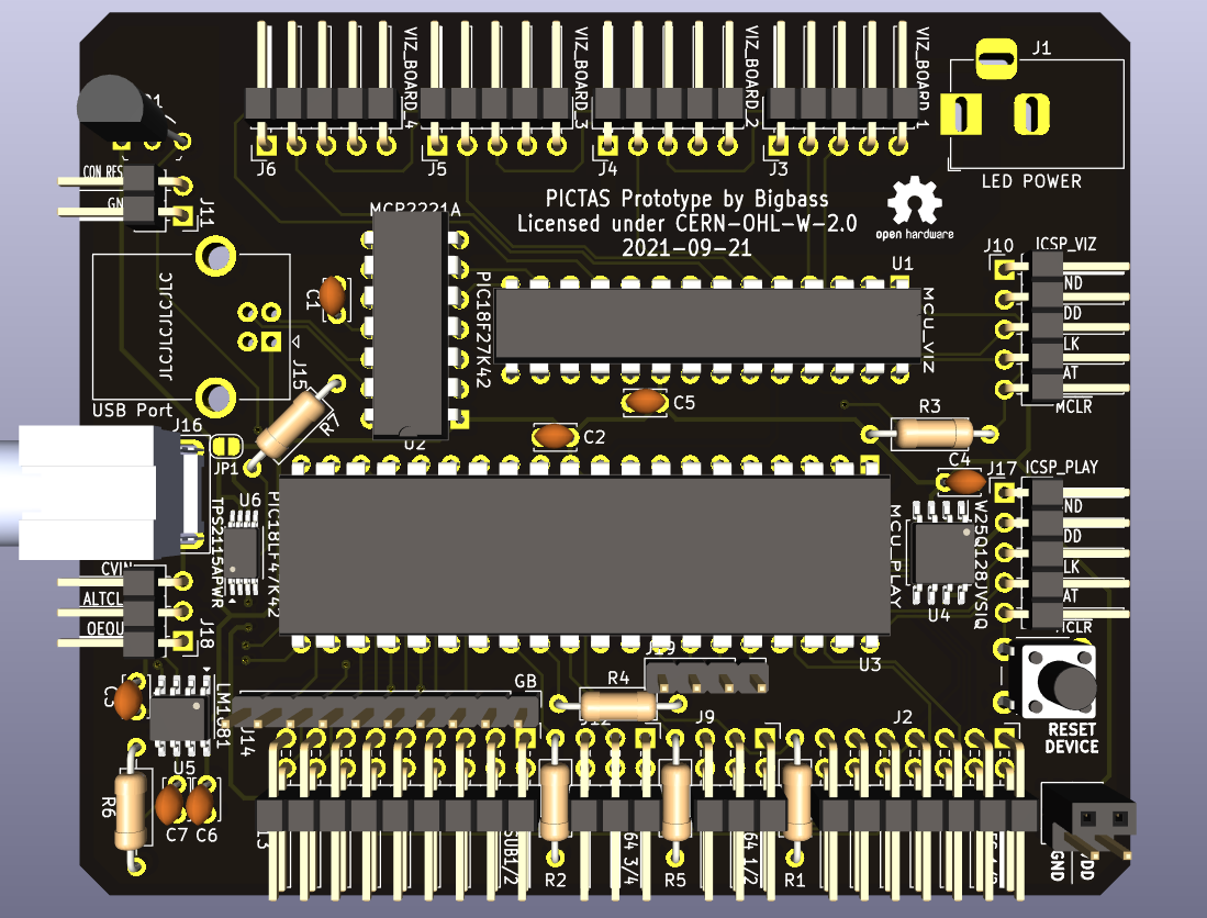
Pictas is an open-source printed circuit board by bigbass1997, from the bigbass1997/PICTAS repository on GitHub. It is a 2-layer board of 74.9 × 89.2 mm with 37 parts on 83 nets, routed with 482 tracks and 24 vias.
It is built around the PIC18F27K42-I/SS, PIC18LF47K42-I/P and LM1881, with the MCP2221A-I/P, W25Q128JVSIQ and BC546 among its other parts. Its parts include 15 connectors, 7 capacitors, 5 ICs, 4 resistors and 2 transistors. It belongs with the PIC boards of this library.


The PICTAS is an input device used to replay Tool-Assisted-Speedruns (aka Tool-Assisted-Superruns) on physical hardware.
A PIC18F47K42 microcontroller is used for the replay portion of the device, and the smaller PIC18F27K42 is used for controlling the input displays.
Unlike a typical TAS replay device, this one stores the TAS inputs on-board, using serial flash memory (W25Q128JVSIQ), capable of storing 16 MB of input data. The advantage is that USB communication is not required during replay. It simplifies the replay process, and greatly reduces the chance of corrupted inputs. Additionally, once programmed, the device can be used without a USB host computer (WIP feature).
This project is still a prototype under heavy development. While I will offer help and support as best I can, please understand that significant code and design changes can occur at any time.
The general process looks like this: Load movie into a host interface. Program the movie's inputs and config options onto the PICTAS device. Finally, use one of the available start methods to begin the playback.
Refer to the PICTAS-Interface project for details on how to use that software. Anyone is free to make their own interface software. There will be docs provided here once the communication protocol has stablized. The PICTAS communicates over USB at a 500,000 baud rate. Single byte commands are initiated from the interface. The PICTAS will respond with one or more bytes.
Because the input data is saved onto the device, you will not need to reprogram it again unless you wish to change the TAS inputs or other configuration data.
0x000000 - 0xFFEFFF | Sequential controller inputs
0xFFF000 - 0xFFF0FF | Config options
0xFFF100 - 0xFFFFFF | Frame-numbered commands
All except the last sector (4KB) of memory, is dedicated to storing the TAS inputs. Format will depend on the console and how many controllers are used. Within the last sector, the first 256 bytes are for config options, while the rest is for special commands that are performed on specific frame numbers.
Each command is made up of a 3 byte wide number, which specifies the frame number. And then a 1 byte command.
0x00 | Console Reset
0x01 | Console Power off and on

0xFF | NullThis replay device also supports input displays (aka viz/visualization boards), providing the viewers a way see which inputs are being pressed in real time.
The displays are designed to be placed on a SPI bus, where each display board shares the same clock and serial signals. Each device uses it's own Chip Select signal as a data latch.
An auxilary power supply must be connected for these displays. The PCB design is rated for a maximum of 2Amps.
If you have questions or suggestions, you can find me on the N64brew Discord server or the TASBot server.
| Qty | Value | Footprint | References |
|---|---|---|---|
| 7 | 0.1uF | Capacitor_THT:C_Disc_D3.4mm_W2.1mm_P2.50mm | C1, C2, C3, C4, C5, C6, C7 |
| 2 | 1K | Resistor_THT:R_Axial_DIN0207_L6.3mm_D2.5mm_P10.16mm_Horizontal | R2, R3 |
| 2 | SolderJumper_2_Open | Jumper:SolderJumper-2_P1.3mm_Open_TrianglePad1.0x1.5mm | JP1, JP2 |
| 1 | 10K | Resistor_THT:R_Axial_DIN0207_L6.3mm_D2.5mm_P10.16mm_Horizontal | R1 |
| 1 | 680k | Resistor_THT:R_Axial_DIN0207_L6.3mm_D2.5mm_P10.16mm_Horizontal | R4 |
| 1 | AUX_FLASH | Connector_PinHeader_2.54mm:PinHeader_1x04_P2.54mm_Vertical | J15 |
| 1 | AUX_VDD_GND_1 | Connector_PinHeader_2.54mm:PinHeader_1x02_P2.54mm_Vertical | J2 |
| 1 | AUX_VDD_GND_2 | Connector_PinSocket_2.54mm:PinSocket_1x02_P2.54mm_Vertical | J3 |
| 1 | BC546 | Package_TO_SOT_THT:TO-92_Inline | Q1 |
| 1 | BC556 | Package_TO_SOT_THT:TO-92_Inline | Q2 |
| 1 | CONTROLLER_PORT | pictas:L77HDA26SD1CH4R | J12 |
| 1 | CON_RESET | Connector_PinHeader_2.54mm:PinHeader_1x03_P2.54mm_Horizontal | J8 |
| 1 | ICSP_PLAY | Connector_PinSocket_2.54mm:PinSocket_1x05_P2.54mm_Horizontal | J13 |
| 1 | ICSP_VIZ | Connector_PinSocket_2.54mm:PinSocket_1x05_P2.54mm_Horizontal | J9 |
| 1 | LED POWER | Connector_BarrelJack:BarrelJack_Horizontal | J1 |
| 1 | LM1881 | Package_SO:SOIC-8_3.9x4.9mm_P1.27mm | U5 |
| 1 | MCP2221A | Package_DIP:DIP-14_W7.62mm | U2 |
| 1 | MCU_RESET | Button_Switch_THT:SW_PUSH_6mm_H7.3mm | SW1 |
| 1 | PIC18F27K42 | Package_DIP:DIP-28_W7.62mm | U1 |
| 1 | PIC18LF47K42 | Package_DIP:DIP-40_W15.24mm | U3 |
| 1 | SYNC | Connector_PinHeader_2.54mm:PinHeader_1x03_P2.54mm_Horizontal | J14 |
| 1 | USB Port | Connector_USB:USB_B_OST_USB-B1HSxx_Horizontal | J10 |
| 1 | VIDEO IN | pictas:PJRAN1X1U04X | J11 |
| 1 | VIZ_BOARD_1 | Connector_PinHeader_2.54mm:PinHeader_1x05_P2.54mm_Horizontal | J4 |
| 1 | VIZ_BOARD_2 | Connector_PinHeader_2.54mm:PinHeader_1x05_P2.54mm_Horizontal | J5 |
| 1 | VIZ_BOARD_3 | Connector_PinHeader_2.54mm:PinHeader_1x05_P2.54mm_Horizontal | J6 |
| 1 | VIZ_BOARD_4 | Connector_PinHeader_2.54mm:PinHeader_1x05_P2.54mm_Horizontal | J7 |
| 1 | W25Q128JVSIQ | Package_SO:SOIC-8_5.275x5.275mm_P1.27mm | U4 |
The 36 most common of 37 parts.
bigbass1997/PICTAS
Low-cost replay device for playing back Tool Assisted Speedruns on real hardware

bigbass1997/PICTAS
Low-cost replay device for playing back Tool Assisted Speedruns on real hardware

Wesemane-Industries/808-kick-eurorack
808 kick (bass drum) for eurorack / modular synth

m0xpd/EUCLIDplus
EUCLID+ is a Clock Divider, Oscillator and Rhythm Sequencer for electronic music applications


johnbeardmore/oBeMS
Open source environmental monitoring, automatic meter reading and building management system.


ABDELBARI0/audio-amplifier-01-pcb
A discrete-component audio amplifier PCB designed using KiCad. The project includes the electrical schematic, PCB layout, and a 3D visualization of the board and its component placement.

It measures 74.9 × 89.2 mm and has 2 copper layers, 1.6 mm thick.
37 parts, built around the PIC18F27K42-I/SS, PIC18LF47K42-I/P, LM1881 and MCP2221A-I/P. The full list of its parts is on this page, with links to each part's symbol and footprint where PCBKit's library has them.
From the bigbass1997/PICTAS repository on GitHub, at the commit this page was made from: the board is hardware/pictas-pcb/pictas.kicad_pcb and its schematic hardware/pictas-pcb/pictas.kicad_sch. PCBKit opens the board in the browser, with nothing to install.
Its repository states no licence, so its author keeps all rights: ask bigbass1997 before reusing the design.