2 layers111.3 × 106.4 mm
Super Sixteen v1
matthewcieplak/super-sixteen
Code and schematics for the Super Sixteen Eurorack sequencer
141 parts171

 bgmbzk/ATmega328P-CAN-Controller
ATmega328P based CAN-Bus node with MCP2551 transceiver and 12V-to-5V power regulation for industrial/automotive sensor applications.
CAN Sensor Node is an open-source printed circuit board by bgmbzk, from the bgmbzk/ATmega328P-CAN-Controller repository on GitHub. It is a 2-layer board of 82.3 × 52.5 mm with 11 parts on 26 nets, routed with 103 tracks and 2 vias.
It is built around the ATMEGA328P-PU and L7805. Its parts include 4 capacitors, 3 ICs, 1 connector and 1 crystal. It belongs with the sensors and measurement and radio and wireless boards and the AVR (ATmega, ATtiny) boards of this library.


This project features a general-purpose electronic control board built around the ATmega328P microcontroller, integrated with a MCP2551 CAN transceiver. It is designed for modular sensor integration and robust communication in automotive or industrial "edge" applications.
/Project_Files: KiCad schematic (.kicad_sch) and PCB layout (.kicad_pcb)./Gerber: Production-ready files (Gerber + Drill) for manufacturing./Screenshots: 3D renders and 2D layouts of the board.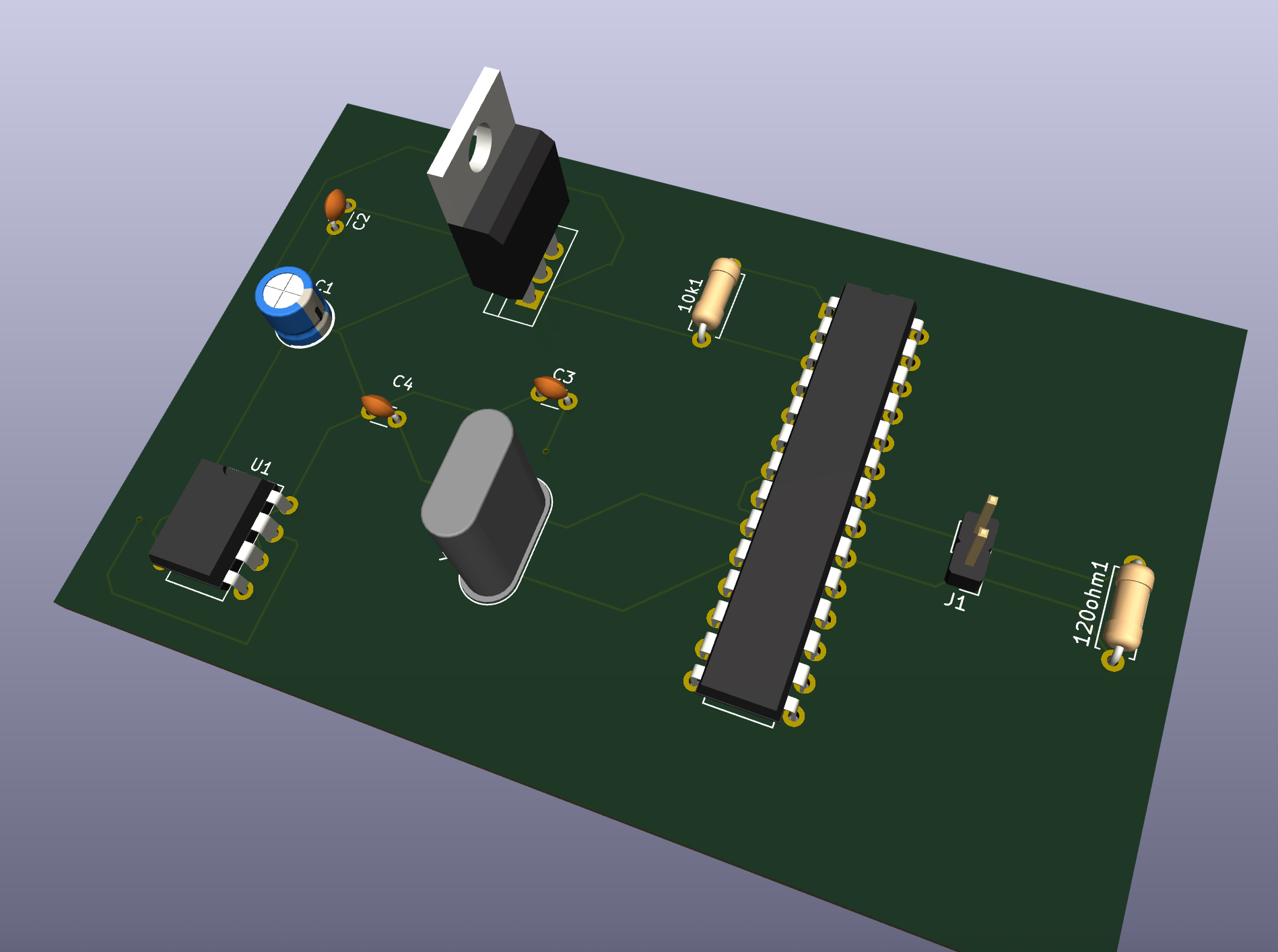
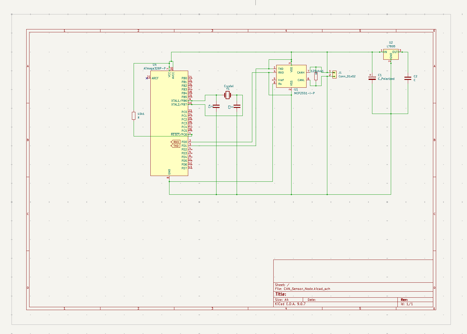
| Qty | Value | Footprint | References |
|---|---|---|---|
| 3 | C | Capacitor_THT:C_Disc_D3.0mm_W1.6mm_P2.50mm | C2, C3, C4 |
| 2 | R | Resistor_THT:R_Axial_DIN0207_L6.3mm_D2.5mm_P7.62mm_Horizontal | 10k1, 120ohm1 |
| 1 | ATmega328P-P | Package_DIP:DIP-28_W7.62mm | U4 |
| 1 | C_Polarized | Capacitor_THT:CP_Radial_D5.0mm_P2.00mm | C1 |
| 1 | Conn_01x02 | Connector_PinHeader_2.54mm:PinHeader_1x02_P2.54mm_Vertical | J1 |
| 1 | Crystal | Crystal:Crystal_HC49-U_Vertical | Y1 |
| 1 | L7805 | Package_TO_SOT_THT:TO-220-3_Vertical | U2 |
| 1 | MCP2551-I-P | Package_DIP:DIP-8_W7.62mm | U1 |
matthewcieplak/super-sixteen
Code and schematics for the Super Sixteen Eurorack sequencer


comakingspace/FlipDotDisplay
They were bought at the Makerfaire Hannover 2016.

RNA-IITPatna/Flight-Controller
Code related to flight controller for RNA's model rockets


It measures 82.3 × 52.5 mm and has 2 copper layers, 1.6 mm thick.
11 parts, built around the ATMEGA328P-PU and L7805. The full list of its parts is on this page, with links to each part's symbol and footprint where PCBKit's library has them.
From the bgmbzk/ATmega328P-CAN-Controller repository on GitHub, at the commit this page was made from: the board is CAN_Sensor_Node.kicad_pcb and its schematic CAN_Sensor_Node.kicad_sch. PCBKit opens the board in the browser, with nothing to install.
Its repository states no licence, so its author keeps all rights: ask bgmbzk before reusing the design.