4 layers150 × 65 mm

 Beo-Coder/muek-TGLBoard3
This project is a small low profile PCB LED matrix that can be used as a name tag or to display various text and animations and to play games.
TGL Board is an open-source printed circuit board by Beo-Coder, from the Beo-Coder/muek-TGLBoard repository on GitHub. It is a 2-layer board of 80 × 32 mm with 185 parts on 187 nets, routed with 1,098 tracks and 196 vias.
It is built around the RP2040, AP2112K-3.3 and WS2812B, with the ABM8G-12.000MHZ-4Y-T3 among its other parts. Its parts include 128 diodes, 29 capacitors, 11 resistors, 3 ICs and 2 connectors. It belongs with the lEDs and displays boards and the RP2040 boards of this library.


This project is a small low profile PCB LED matrix that can be used as a name tag or to display various text and animations and to play games.
If you have your own "programmable" version, you can read more about programming here
This project was initially planned as a gift for teachers after our graduation.
It is a small and low cost LED matrix board.
It consists of a 8x16 ARGB LED matrix, two buttons as user input and a USB-C jack for powering and programming.
On the front and backside there are several places where custom text can be written to,
to further individualize the board.
One of the main goals was that the whole board is visually appealing
and can be used without an enclosure to have a simpler and sleeker looking product.
The electronics consist of an RP2040 microcontroller and a 2 MB (16 Mbit) flash IC.
You can read more about the electronic here
To program the board,
you can use SWD on the Tag-Connect connector on the backside as well as on the custom pads on the backside.
It is also possible to program the board over USB-C,
but this needs further hardware modifications (Read more about here)
Currently, the software has four modes:
Between these modes, you can easily switch by holding down both buttons at the same time and waiting a bit. You can choose the mode by going left or right and select it by either waiting or pressing both buttons again.
Inside the different modes, the two buttons have different meanings. They change the text, the color of the text, the animation, or you can play the game.
The text can be individually programmed by modifying the board_text_config.h file.
There are currently seven different animations:
There are also two games, but only one is selected by default.
To change the game, you need to modify main.cpp.
Left: Duck
Right: Jump
After each game, your score and your high score is shown.
Left: Moves block to the left
Right: Moves block to the right
Right while holding left: Rotating block
After each game, your score and your high score is shown.
This Tetris game was created by @StarMiner99
The brightness is only saved when you switch the menu after setting the desired brightness.
You can either use PlatformIO (Arduino Framework) or the official C/C++ SDK from Raspberry Pi.
If you want to use the C/C++ SDK, please use the c-SDK branch.
For details on how these two differ, read Runtime.
You need PlatformIO to use this project.
Arduino IDE might work too (not tested).
In the platform.ini file, there are now two build environments.
pico_normal and pico_fast you can read about the differences here Runtime.
For your own programming, you can use my pioMatrixOutput library. Documentation is here pioMatrixOutput.
For your own text, you can use my library. Documentation is here Textcontroller.
For flash usage, read here Flash.
Important: If you brick your board (can't upload anything) please read here.
Schematic, layout, BOM and gerber files can be found here.
Each button has a 10k-ohm pull-down resistor and a 100-nF capacitor for debouncing.
The design of the MCU section follows more or less the hardware design guide for the RP2040.
Because of the design,
it was not possible to add a 100-nF capacitor to each LED, but each row of LEDs (16 each) has its own 10-uF cap
(I know it is not perfect or a replacement).
Also,
there are multiple more capacitors to further decouple the matrix as good as possible
so that fast-changing patterns do not affect the MCU and its operations.
This is further improved by the fact the whole MCU subsystem runs on 3.3V over a LDO and not the 5.0V that the LEDs run on.
While testing, I haven't had any issues with noisy power lines.
Also, when measuring with my oscilloscope and the matrix turning fully on and fully off as fast as possible,
I couldn't measure any serious noise on the 5.0V rail nor on the 3.3V rail for the MCU.
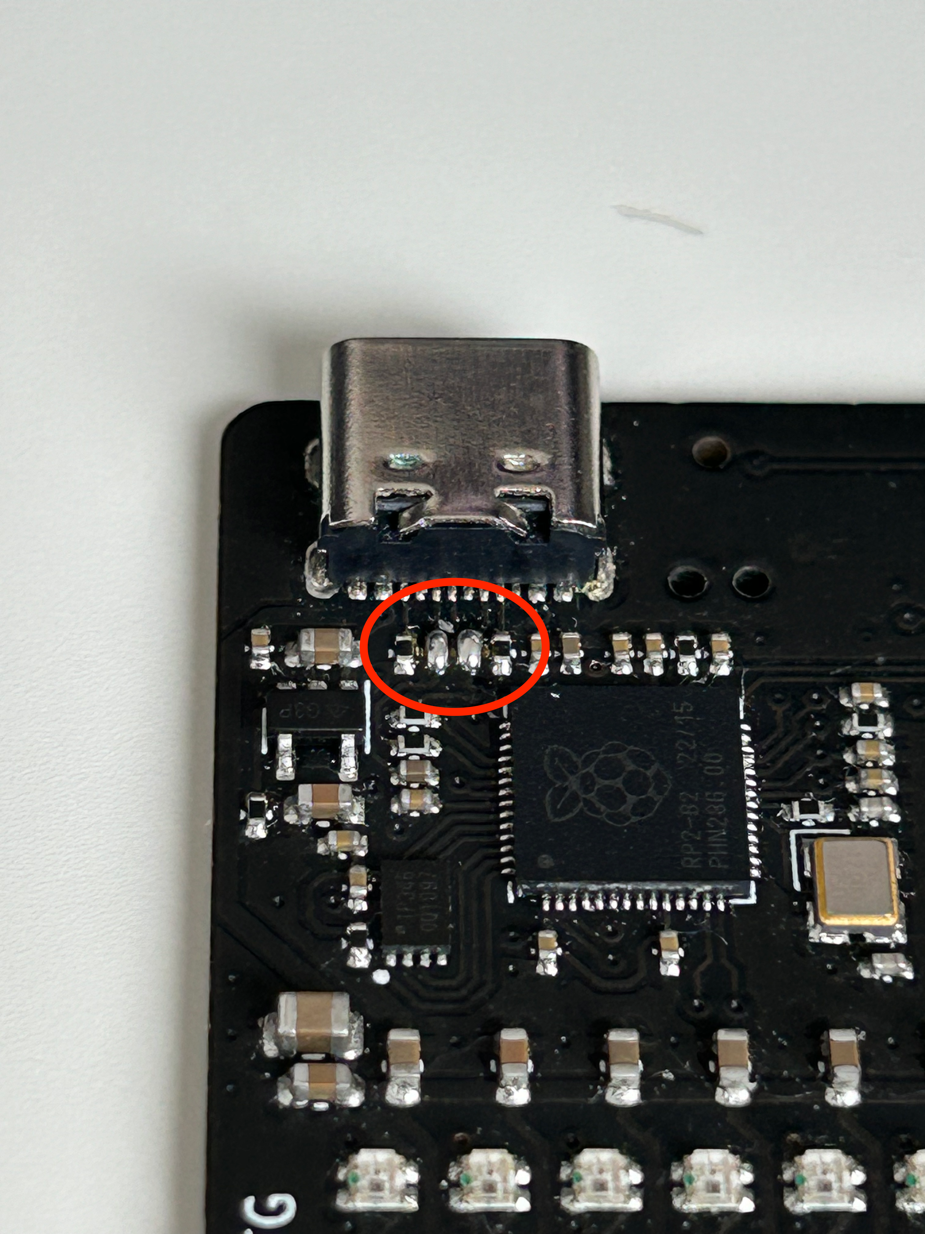
Behind the USB-C jack, there are two unpopulated pads.
These pads cut the USB data signal, so that you can't program the board over USB.
This can be useful, for example,
if you do not want that your teachers get confused when they plug it in to their pc :^)
If you want to enable USB programming,
you need to short these two pads either with an 0402 0-ohm resistor or simply with solder bridges.
Be aware that this is quite challenging to solder, you shouldn't destroy/desolder neighboring components.
Maybe it is easier if you use a hotplate and 0-ohm resistors (Haven't tried it).
If you order new boards, you can add those to be assembled too.
The 27-ohm resistors on each USB data line necessary for the RP2040 are already assembled.
It should look something like this:
The three unnamed pads on the backside above the UART pads are connections for SWD programming.
Pinout:
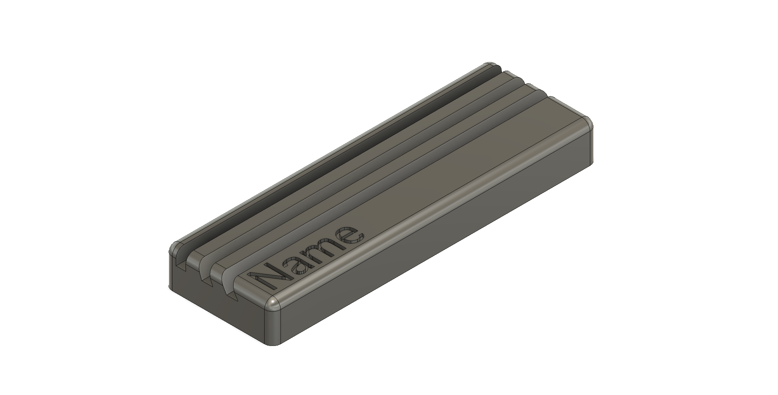
board outline | | +---+ +---+ +---+ | / \ / \ / \ | / \ / \ / \ | + RUN + + SWD + + SWCLK + | \ / \ / \ / | \ / \ / \ / | +---+ +---+ +---+ | | +---+ +---+ | / \ / \ | / \ / \ | + Tx + + Rx + | \ / \ / | \ / \ / | +---+ +---+I also created a stand for the board.
It has three different angles: 90°, 70° and 60°.
It has place for a name on the top side and for text on the bottom side.
Inside the stand there are three slots for 1 cent coins (EU) to make the stand more stable.
If you want to insert those coins, you need to stop the print mid-way and insert/glue the coins in place.
3mf and STL files can be found here
If you have any questions, please contact me.
© 2024 Leonhard Baschang
| Qty | Value | Footprint | References |
|---|---|---|---|
| 128 | WS2812B | LeosLib:LED_WS2812B_XL-1615RGBC-WS2812B | D1, D10, D11, D100, D101, D102, D103, D104, D105, D106, D107, D108, D109, D110, D111, D112 +112 |
| 13 | 100n | Capacitor_SMD:C_0402_1005Metric | C1, C2, C5, C6, C7, C8, C9, C10, C11, C14, C16, C20, C21 |
| 11 | 10u | Capacitor_SMD:C_0603_1608Metric | C15, C17, C18, C22, C23, C24, C25, C26, C27, C28, C29 |
| 3 | 10k | Resistor_SMD:R_0402_1005Metric | R2, R6, R7 |
| 2 | 0 | Resistor_SMD:R_0402_1005Metric | R10, R11 |
| 2 | 15p | Capacitor_SMD:C_0402_1005Metric | C12, C13 |
| 2 | 1u | Capacitor_SMD:C_0402_1005Metric | C3, C4 |
| 2 | 27 | Resistor_SMD:R_0402_1005Metric | R8, R9 |
| 2 | 5.1k | Resistor_SMD:R_0402_1005Metric | R3, R4 |
| 1 | 100k | Resistor_SMD:R_0402_1005Metric | R5 |
| 1 | 1k | Resistor_SMD:R_0402_1005Metric | R1 |
| 1 | 3.3V | TestPoint:TestPoint_Pad_D1.0mm | TP7 |
| 1 | 47u | Capacitor_SMD:C_0805_2012Metric | C19 |
| 1 | 5.0V | TestPoint:TestPoint_Pad_D1.0mm | TP8 |
| 1 | ABM8G-12.000MHZ-4Y-T3 | Crystal:Crystal_SMD_3225-4Pin_3.2x2.5mm | Y1 |
| 1 | AP2112K-3.3 | Package_TO_SOT_SMD:SOT-23-5 | U2 |
| 1 | Button 1 | PTS526:PTS526SK15SMTR2LFS | S1 |
| 1 | Button 2 | PTS526:PTS526SK15SMTR2LFS | S2 |
| 1 | Conn_ARM_SWD_TagConnect_TC2030-NL | Connector:Tag-Connect_TC2030-IDC-NL_2x03_P1.27mm_Vertical | J1 |
| 1 | GND | TestPoint:TestPoint_Pad_D1.0mm | TP6 |
| 1 | LOGO | customLogos:muehkLogo | G*** |
| 1 | RP2040 | Package_DFN_QFN:QFN-56-1EP_7x7mm_P0.4mm_EP3.2x3.2mm | U1 |
| 1 | RUN | TestPoint:TestPoint_Pad_D1.0mm | TP1 |
| 1 | Rx | TestPoint:TestPoint_Pad_D1.0mm | TP3 |
| 1 | SWCLK | TestPoint:TestPoint_Pad_D1.0mm | TP4 |
| 1 | SWD | TestPoint:TestPoint_Pad_D1.0mm | TP5 |
| 1 | Tx | TestPoint:TestPoint_Pad_D1.0mm | TP2 |
| 1 | USB_C_Receptacle_USB2.0_16P | Connector_USB:USB_C_Receptacle_GCT_USB4105-xx-A_16P_TopMnt_Horizontal | J2 |
| 1 | W25Q16JVUXIQ_TR | W25Q16JVUXIQ:SON50P300X200X60-9L | IC1 |
It measures 80 × 32 mm and has 2 copper layers, 1.6 mm thick.
185 parts, built around the RP2040, AP2112K-3.3, WS2812B and ABM8G-12.000MHZ-4Y-T3. The full list of its parts is on this page, with links to each part's symbol and footprint where PCBKit's library has them.
From the Beo-Coder/muek-TGLBoard repository on GitHub, at the commit this page was made from: the board is hardware/KiCAD/TGL_Board.kicad_pcb and its schematic hardware/KiCAD/MatrixModule.kicad_sch. PCBKit opens the board in the browser, with nothing to install.
Its repository states no licence, so its author keeps all rights: ask Beo-Coder before reusing the design.

CafeAsh/DevBoards
Development board based on the ATmega32U4 microcontroller, designed for USB-enabled embedded projects, rapid prototyping, and firmware experimentation.


Aharoni-Lab/Miniscope-Wire-Free-DAQ
All information, guides, and tutorials can be found on the Miniscope-Wire-Free-DAQ Wiki Page .

EggiEl/SpiCy-BEXUS
Cyanobacteria are among the oldest and most efficient photosynthetic organisms on planet Earth. They contribute 25% of the oxygen on Earth today and were crucial in forming our atmosphere in the early stages of Earth's…

