2 layers75 × 75 mm

 bennytrouser/NostrumX19
A 32 key ergonomic split keyboard using Seeed Xiao BLE
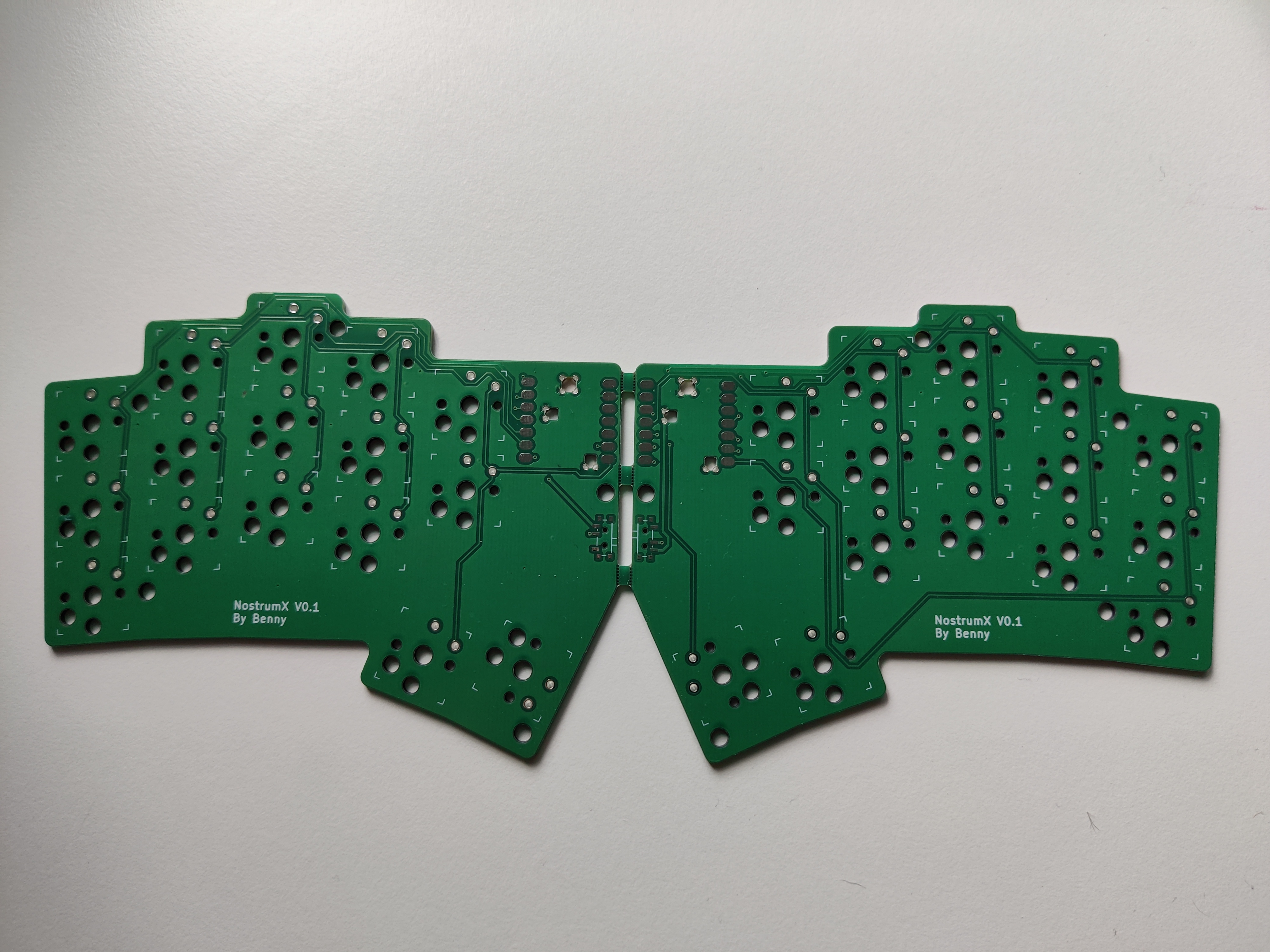
NostrumX2 is an open-source printed circuit board by bennytrouser, from the bennytrouser/NostrumX repository on GitHub, published under the MIT licence. It is a 2-layer board of 233.6 × 89.5 mm with 90 parts on 70 nets, routed with 664 tracks and 29 vias.
Its parts include 34 switches and 32 diodes. It belongs with the keyboards and input and radio and wireless boards of this library.
A 32 key ergonomic split keyboard using Seeed Xiao BLE
This keyboard is a variation on my original Nostrum using a Seeeduino Xiao BLE with the battery mounted under the PCB within the case. Not designed to be used without the case.
The aim was to create a case based board while maintaining as much of the original shape and clean lines of the original nostrum pcb.
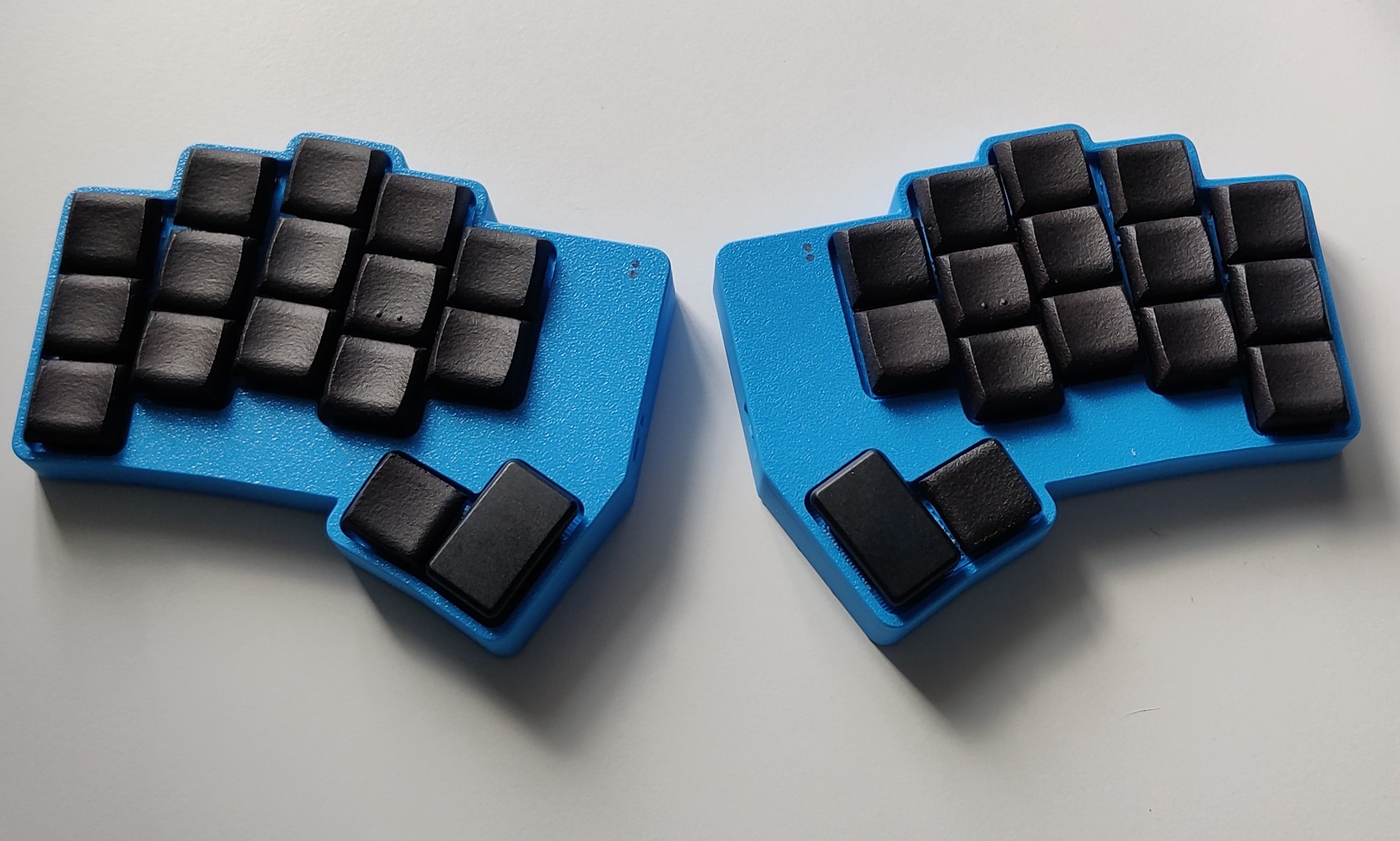
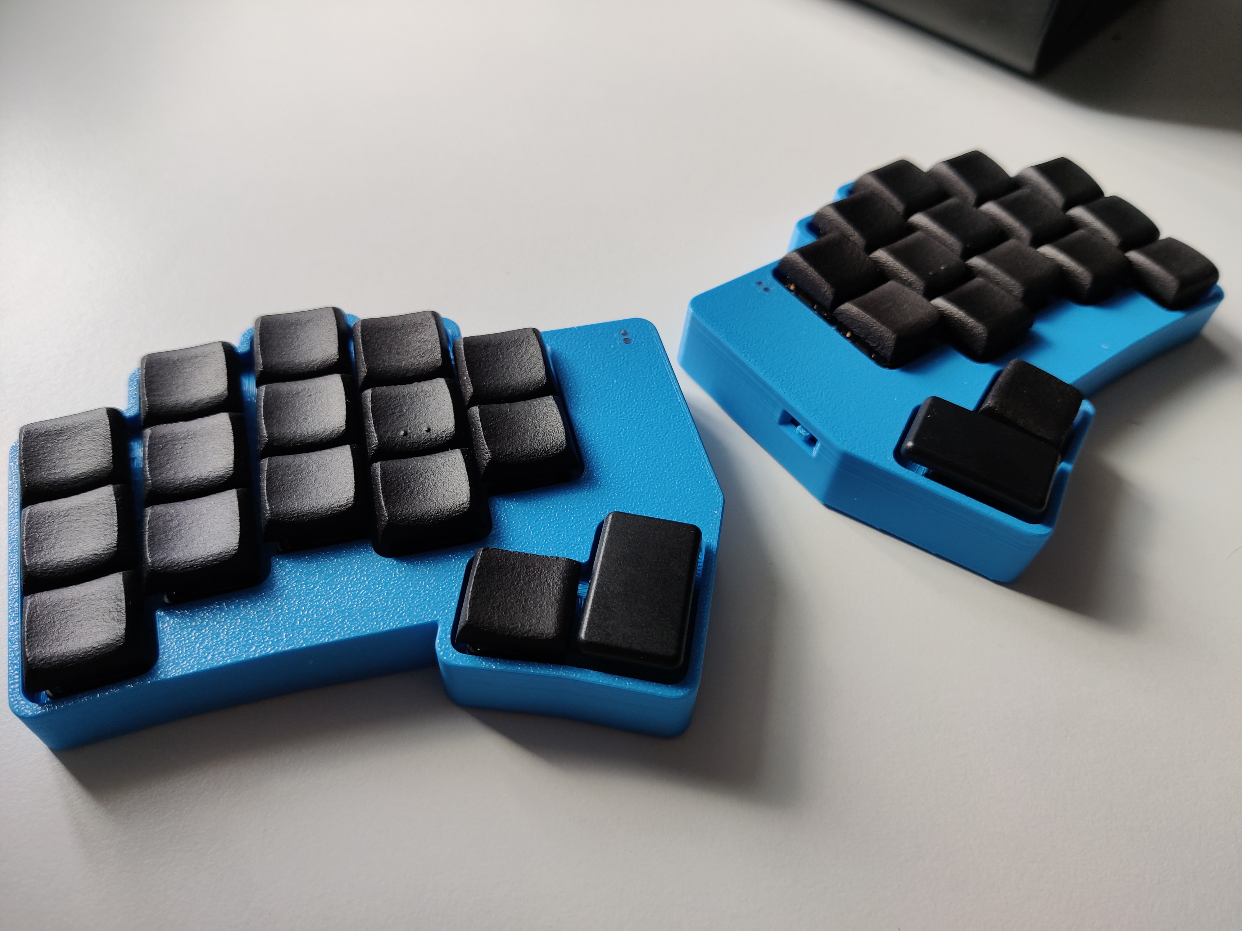
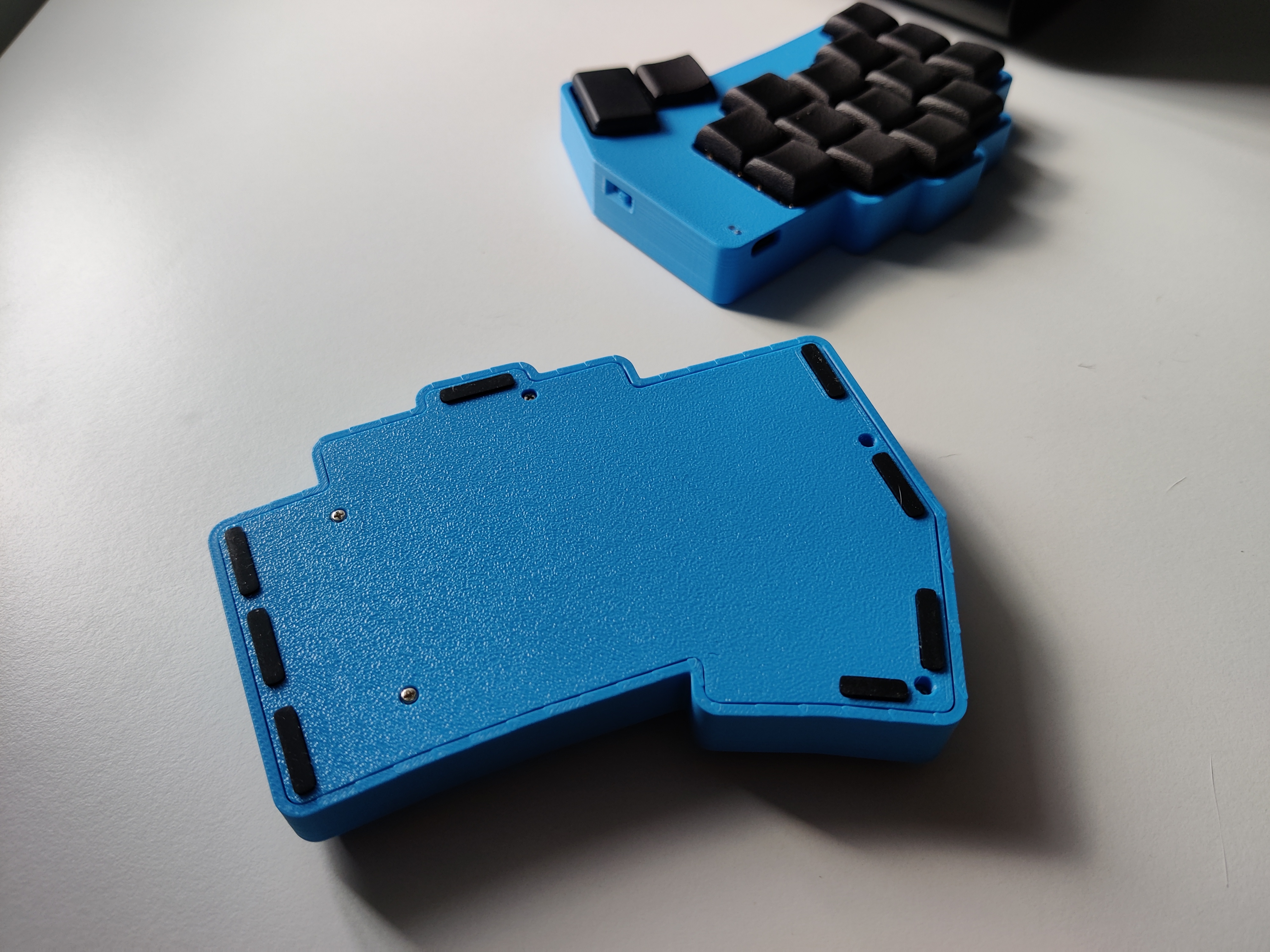
The case is designed to be fastened from the underside using M1.5x6mm self tapping screws. Feet used are 10x3x1.5mm and 14x3x1.5mm. Left side has space to fit a lipo Battery 402030(180mah). Due to constraints, the right side will need a narrower battery if using hotswap. For my build, I used a 401322 (120mah) but a different size may fit. Example parts listed below. Source your switches and sockets and MCUs where available.
| Part | Link |
|---|---|
| Battery 402030 | https://www.ebay.co.uk/itm/355875616696 |
| Battery 401322 | https://www.ebay.co.uk/itm/195234785175 |
| Self tapping Screws M1.5x6mm | https://www.aliexpress.com/item/1005005469153402.html |
| SMD diodes SOD-123 1N4148W T4 | https://www.aliexpress.com/item/32948518338.html |
| 1.5mm Fibreoptic cable (for led shinethrough) | https://www.aliexpress.com/item/1005005886250822.html |
| Reset button TL3342 | https://www.aliexpress.com/item/1005007506687094.html |
| Power switch PCM12 | https://www.aliexpress.com/item/32912838968.html |
| Feet | https://www.aliexpress.com/item/1005006691343859.html |
Designed in Fusion360. 3d printed. Recommended to print the top case with face down for texured finish. There are two different bottoms, with or without a hole for a reset switch depending on if you want to use one.
The Switch bits need to be fitted before installing the pcb and are a tight fit. Also may require a bit of jiggling to get the slider to seat correctly on install.
The holes on the top of the case allow the charge led and the user led to shine through. I have used fibre optic cable in these holes but it is optional and a tight fit that may require slight enlargement with a screwdriver or small drillbit for the cable to slide in. Any larger in the file and it's a little loose.
| Qty | Value | Footprint | References |
|---|---|---|---|
| 32 | PG1350 | S1, S2, S10, S11, S12, S13, S14, S15, S16, S17, S18, S19, S20, S21, S22, S23 +16 | |
| 32 | ComboDiode | D1, D2, D10, D11, D12, D13, D14, D15, D16, D17, D18, D19, D20, D21, D22, D23 +16 | |
| 6 | Breakaway Tabs | Library:Breakaway_Tabs_Med | LH1, LH2, LH3, RH1, RH2, RH3 |
| 4 | SMDPad | PAD1, PAD2, PAD3, PAD4 | |
| 2 | Button_Switch_SMD:SW_SPST_TL3342 | B1, B2 | |
| 2 | xxLib:MCU_xiao-ble-smd | , | |
| 2 | Button_Switch_SMD:SW_SPDT_PCM12 | SW1, SW2 | |
| 1 | MountingHole_3.2mm_M3 | MountingHole:MountingHole_3.2mm_M3 | Mount |
The 81 most common of 90 parts.

carrefinho/forager
34-key wireless split keyboard inspired by ZSA Voyager

PantsForBirds/adsbee
Open Source Embedded ADS-B Receiver


siderakb/ergo-snm-keyboard
ErgoSNM is a split ergonomic keyboard integrated with trackball, wireless is in beta

zynthian/zynthian-hw
Zynthian hardware stuff: PCBs, schemes, parts specifications, pin assignment, ...

It measures 233.6 × 89.5 mm and has 2 copper layers, 1.6 mm thick.
90 parts. The full list of its parts is on this page, with links to each part's symbol and footprint where PCBKit's library has them.
From the bennytrouser/NostrumX repository on GitHub, at the commit this page was made from: the board is Pcb/nostrumX2.kicad_pcb. PCBKit opens the board in the browser, with nothing to install.
Its repository publishes it under the MIT licence: you may reuse it on that licence's terms (keep the author's notice, and for a copyleft licence share your changes alike).