2 layers60 × 30 mm
 benhoff/lux-sensor
USB ambient light sensor based on a CH552G MCU and VEML7700 ALS, with:
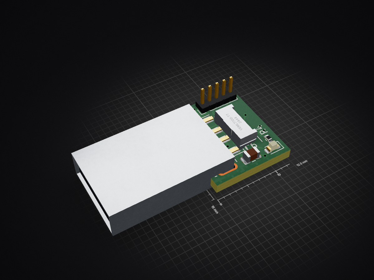
Lux sensor is an open-source printed circuit board by benhoff, from the benhoff/lux-sensor repository on GitHub. It is a 4-layer board of 12.5 × 15 mm with 16 parts on 22 nets, routed with 150 tracks and 20 vias.
It is built around the CH543D and VEML7700-TT. Its parts include 6 capacitors, 4 resistors, 2 ICs, 2 connectors and 1 diode. It belongs with the sensors and measurement boards and the 8051 (CH55x, STC, AT89) boards of this library.


USB ambient light sensor based on a CH552G MCU and VEML7700 ALS, with:
USB CDC ACMlux-sensor.kicad_sch, lux-sensor.kicad_pcb, lux-sensor.kicad_pro: hardware sourcefirmware/: CH552 firmware and build ruleshost/: Linux daemon and service exampleBOM.csv, BOM_PCBWay.csv, BOM_NOTES.md: purchasing and assembly notes*.pretty/, *.kicad_mod, *.kicad_sym: local footprint and symbol assetsCH552DS1.pdf, VEML7700.pdf: datasheet references used during designSCHEMATIC_REVIEW.md: electrical review notes and known design considerationsPOWER_PASSIVES_REVIEW.md: CH543D USB-A 5 V power passive recommendationsGenerated fabrication exports and firmware build artifacts are intentionally ignored by Git.
Core parts:
CH552GVEML7700-TRThe board is intended to enumerate as a USB serial device and stream lines such as:
raw=2468 lux=123.40Build requirements:
sdccmakepackihxobjcopyBuild:
make -C firmwareUpload with the factory bootloader tooling:
make -C firmware uploadThe Linux-side daemon reads the CDC ACM stream and writes brightness through the kernel backlight interface.
Dry run:
python3 host/luxd.py --dry-run --verboseRun against the real backlight node:
sudo python3 host/luxd.pySee firmware/README.md and host/README.md for the full firmware and daemon details.
| Qty | Value | Footprint | References |
|---|---|---|---|
| 2 | 1uF | Capacitor_SMD:C_0603_1608Metric | C4, C5 |
| 2 | 4.7k | Resistor_SMD:R_0603_1608Metric | R1, R2 |
| 1 | 100nF | Capacitor_SMD:C_0805_2012Metric | C3 |
| 1 | 100nF | Capacitor_SMD:C_0603_1608Metric | C2 |
| 1 | 10k | Resistor_SMD:R_0603_1608Metric | R3 |
| 1 | 10u | Capacitor_SMD:C_0603_1608Metric | C1 |
| 1 | 10u | Capacitor_SMD:C_0805_2012Metric | C6 |
| 1 | 4.7k | Resistor_SMD:R_0402_1005Metric | R4 |
| 1 | CH543D | ch543:QFN-20-1EP_3x3mm_P0.4mm_EP1.7x1.7mm_CH543D | U2 |
| 1 | Conn_01x05_Pin | Connector_PinHeader_1.27mm:PinHeader_1x05_P1.27mm_Vertical | J2 |
| 1 | Jumper_2_Open | Jumper:SolderJumper-2_P1.3mm_Open_Pad1.0x1.5mm | JP1 |
| 1 | LED | LED_SMD:LED_0603_1608Metric | D1 |
| 1 | USB_A | Connector_USB:USB_A_Molex_48037-2200_Horizontal | J1 |
| 1 | VEML7700-TT | C1850416:ALS-SMD_4P-L6.8-W2.4_VEML7700-TT_TopView | U1 |
It measures 12.5 × 15 mm and has 4 copper layers, 1.6 mm thick.
16 parts, built around the CH543D and VEML7700-TT. The full list of its parts is on this page, with links to each part's symbol and footprint where PCBKit's library has them.
From the benhoff/lux-sensor repository on GitHub, at the commit this page was made from: the board is lux-sensor.kicad_pcb and its schematic lux-sensor.kicad_sch. PCBKit opens the board in the browser, with nothing to install.
Its repository states no licence, so its author keeps all rights: ask benhoff before reusing the design.


espena/broadcast-clock
Digital precision studio/broadcast masterclock with WiFi configuration, acts as local NTP server with accurate GPS time sync.


teapotlaboratories/bwlr3d
Teapot BWLR3D: Asset Tracker and Environmental Sensor with Solar Energy Harvesting

proveskit/solar_boards
The solar panel boards for the PROVES Kit

MuffinByteLabs/esp32s3-plant-monitor
Portfolio PCB: ESP32-S3 Wi-Fi plant monitor. 4-layer KiCad 10 design, fabricated and assembled at JLCPCB — schematic, reviews and the frozen manufacturing package all readable in-browser.

AvansETI/SmartSensor
SmartSensor: a sensor to be used as sensor and actuator within existing buildings.