
4 layers57.2 × 50.8 mm

 belenseptian/RS485LP
RS-485LP is an open-source RS485 converter featuring a custom PCB and optimized PlatformIO firmware. It is designed to minimize power consumption for battery-operated sensors and remote monitoring systems.
Rs485-lowpower is an open-source printed circuit board by belenseptian, from the belenseptian/RS485LP repository on GitHub, published under the GPL-3.0 licence. It is a 2-layer board of 45.4 × 31.7 mm with 17 parts on 12 nets, routed with 200 tracks and 16 vias.
It is built around the MAX485CSA+T. Its parts include 8 resistors, 2 capacitors, 1 IC and 1 diode. It belongs with the interfaces and adapters boards and the ESP32 boards of this library.
RS-485LP is an open-source RS485 converter featuring a custom PCB and optimized PlatformIO firmware. It is designed to minimize power consumption for battery-operated sensors and remote monitoring systems.
🔗 Official Project Website: https://belenseptian.github.io/RS485LP/
Below are the top and bottom views of the RS-485LP PCB.
| Top View (Components) | Bottom View (Traces) |
|---|---|
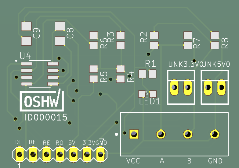 | 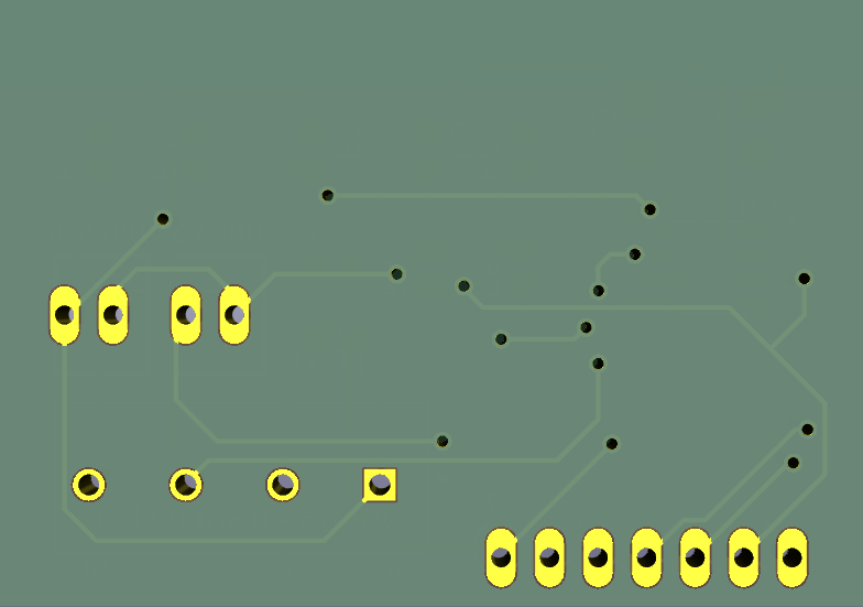 |
The PCB design is created using KiCad. You can find the project files in the pcb/ directory.
Most modern PCB manufacturers allow you to upload the KiCad file directly:
.kicad_pcb file from the pcb/ folder directly to PCBWay's Instant Quote..zip file to the manufacturer.This project uses PlatformIO inside Visual Studio Code.
git clone https://github.com/belenseptian/RS485LP.gitfirmware/ folder and select it.115200).| Pin Name | Description | Connection |
|---|---|---|
| VCC | Power Input | Depend on the sensor specifications |
| GND | Ground | Ground |
| A | RS485 Data+ | Connect to Bus A |
| B | RS485 Data- | Connect to Bus B |
RS-485LP/
├── firmware/           # PlatformIO project files
│   ├── src/            # Main application code (Sleep/Shutdown logic)
│   └── platformio.ini  # Project configuration
├── pcb/                # KiCad project files (.kicad_pcb, .kicad_sch)
├── docs/               # Datasheets and additional documentation
└── README.md # This fileThis project is licensed under the GNU General Public License v3.0 - see the LICENSE file for details.
Contributions are welcome! If you have suggestions for better power-gating or further reducing shutdown current, feel free to open an Issue or submit a Pull Request.
Developed by Belen Septian
| Qty | Value | Footprint | References |
|---|---|---|---|
| 4 | 10k | R0805_334 | R3, R4, R5, R6 |
| 2 | 20k | R0805_334 | R7, R8 |
| 2 | VAC | 22-23-2021_165 | UNK3.3V0, UNK5V0 |
| 1 | MA07-1_162 | MCU0 | |
| 1 | SML0805_259 | LED1 | |
| 1 | 0.1u | C1206_334 | C9 |
| 1 | 10u | C1206_334 | C8 |
| 1 | 120 | R0805_334 | R2 |
| 1 | 1k | R0805_334 | R1 |
| 1 | 282837-4 | TE_282837-4 | RS485-UGMLPV1.0 |
| 1 | ID000015 | CERT-SMALL-SILK | U$1 |
| 1 | MAX485CSA+T | SOIC127P600X175-8N | U4 |


hoglet67/RGBtoHDMI
Bare-metal Raspberry Pi project that provides pixel-perfect sampling of Retro Computer RGB/YUV video and conversion to HDMI


hackclub/OnBoard
💡 Join 1,000 teenagers and make your first PCB with a $100 grant!

DDeGonge/OS-ARM
This arm is not industrial and it will not be fast, but that is not my goal. But it will hopefully be a very nice looking arm fully capable of 6dof motion, cheap enough to keep it accessable but capable enough to…

It measures 45.4 × 31.7 mm and has 2 copper layers, 1.6 mm thick.
17 parts, built around the MAX485CSA+T. The full list of its parts is on this page, with links to each part's symbol and footprint where PCBKit's library has them.
From the belenseptian/RS485LP repository on GitHub, at the commit this page was made from: the board is pcb/rs485-lowpower.kicad_pcb and its schematic pcb/rs485-lowpower_1.kicad_sch. PCBKit opens the board in the browser, with nothing to install.
Its repository publishes it under the GPL-3.0 licence: you may reuse it on that licence's terms (keep the author's notice, and for a copyleft licence share your changes alike).