
2 layers160 × 100 mm

Poor man's Optical Power Converter
LED is an open-source printed circuit board by BehrensG, from the BehrensG/PMOPC repository on GitHub. It is a 2-layer board of 148 × 100 mm with 35 parts on 20 nets, routed with 38 tracks and 139 vias.
It is built around the TSR 1-2450E and CSD18501Q5A. Its parts include 14 resistors, 8 diodes, 5 capacitors, 2 ICs and 1 transistor.


Poor man's Optical Power Converter
Lately, I have come across the concept of Optical Power Converters (OPC), also known as Photonic Power Converters (PPC), which supply power to circuits using light and fiber optics. This technology is interesting to me for three main reasons: voltage isolation, immunity to common-mode noise and low noise output. For more information about OPC/PPC check : What is an Optical to Electrical Converter?. Commercial OPCs can deliver up to 3 W of power. However, the main drawback is that these devices are expensive — with receiver prices starting at approximately 500 euros and transmitters costing around 1,000 euros — and they are not easy to obtain. You can only get Broadcom products on Mouser or DigiKey. A cheap alternative is to use a laser diode, plastic optical fiber, and a photodiode, as described in this paper on isolated sensor networks : Isolated sensor networks for high-voltage environments using a single polymer optical fiber and LEDs for remote powering as well as data transmission. The downside to this photodiode approach is the limited output power, which is measured only in milliwatts. To overcome these limitations, the solution I would like to test is using infrared LEDs to shine on photovoltaic cells to generate output power.
Design was done using KiCAD 10.
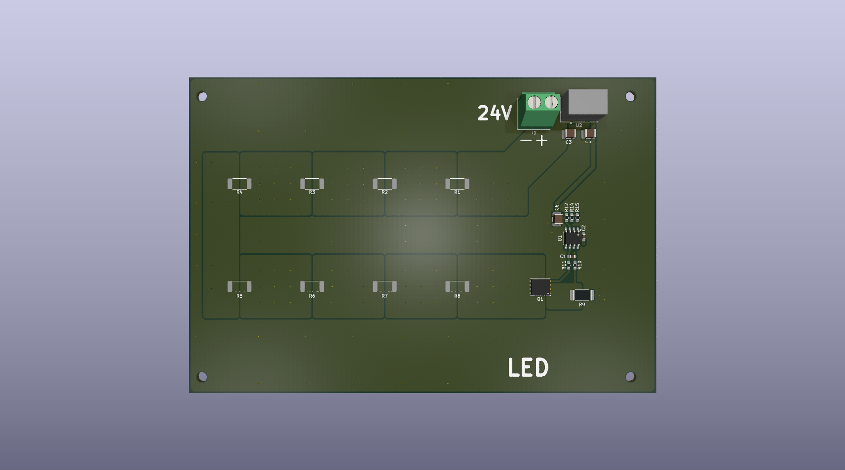
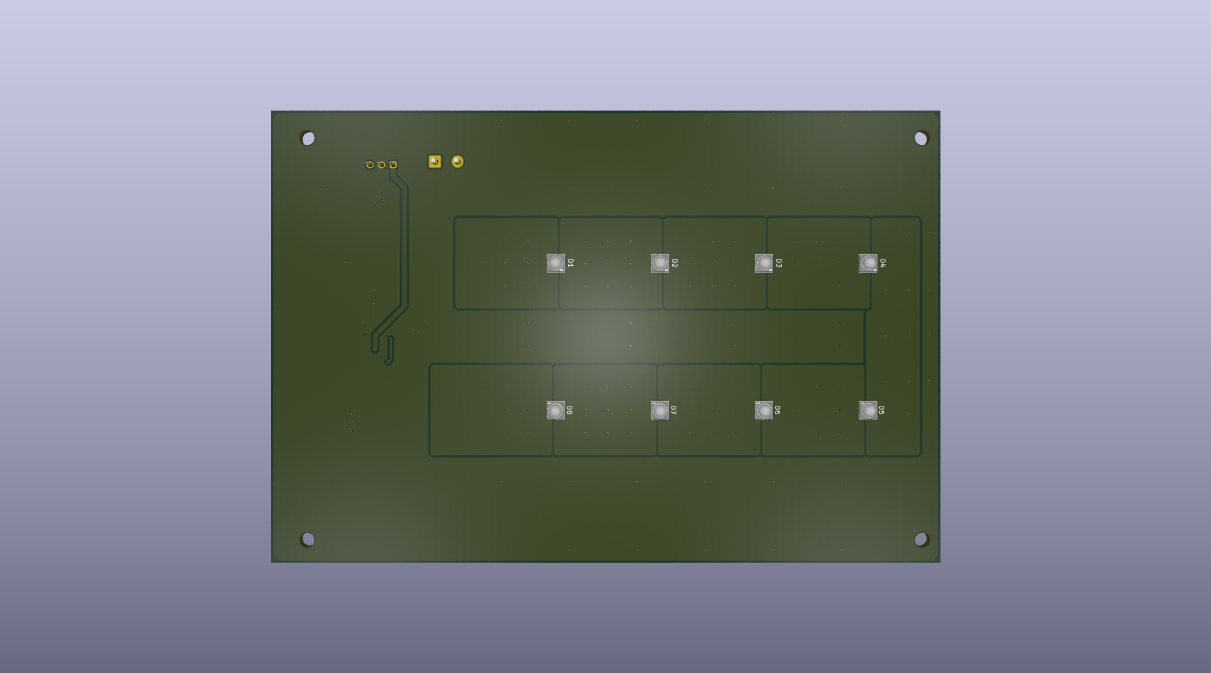
Two layer PCB with 8x SFH 4715AS LEDs controlled with a current source.
Two layer PCB with 2x6 solar cell matrix using SM111K09L.
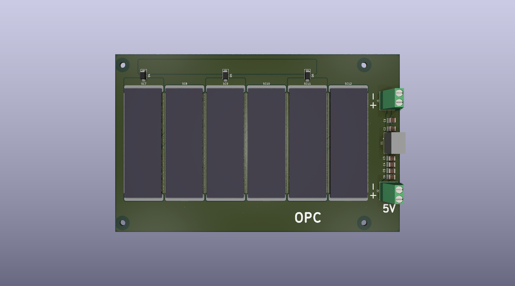
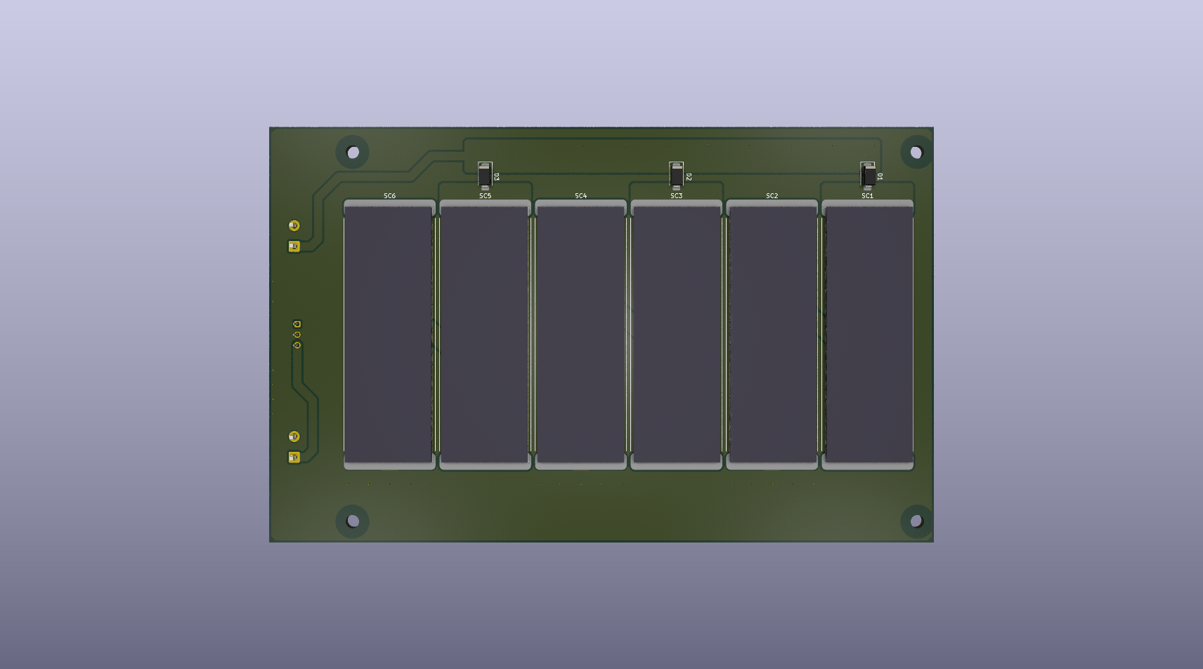
I mounted only four solar cells due to the layout of the LED board design. Since each solar cell requires two LEDs and the LED board accommodates a maximum of eight LEDs, four cells is the limit. The 8 LED limits is because I want to use 24V max.
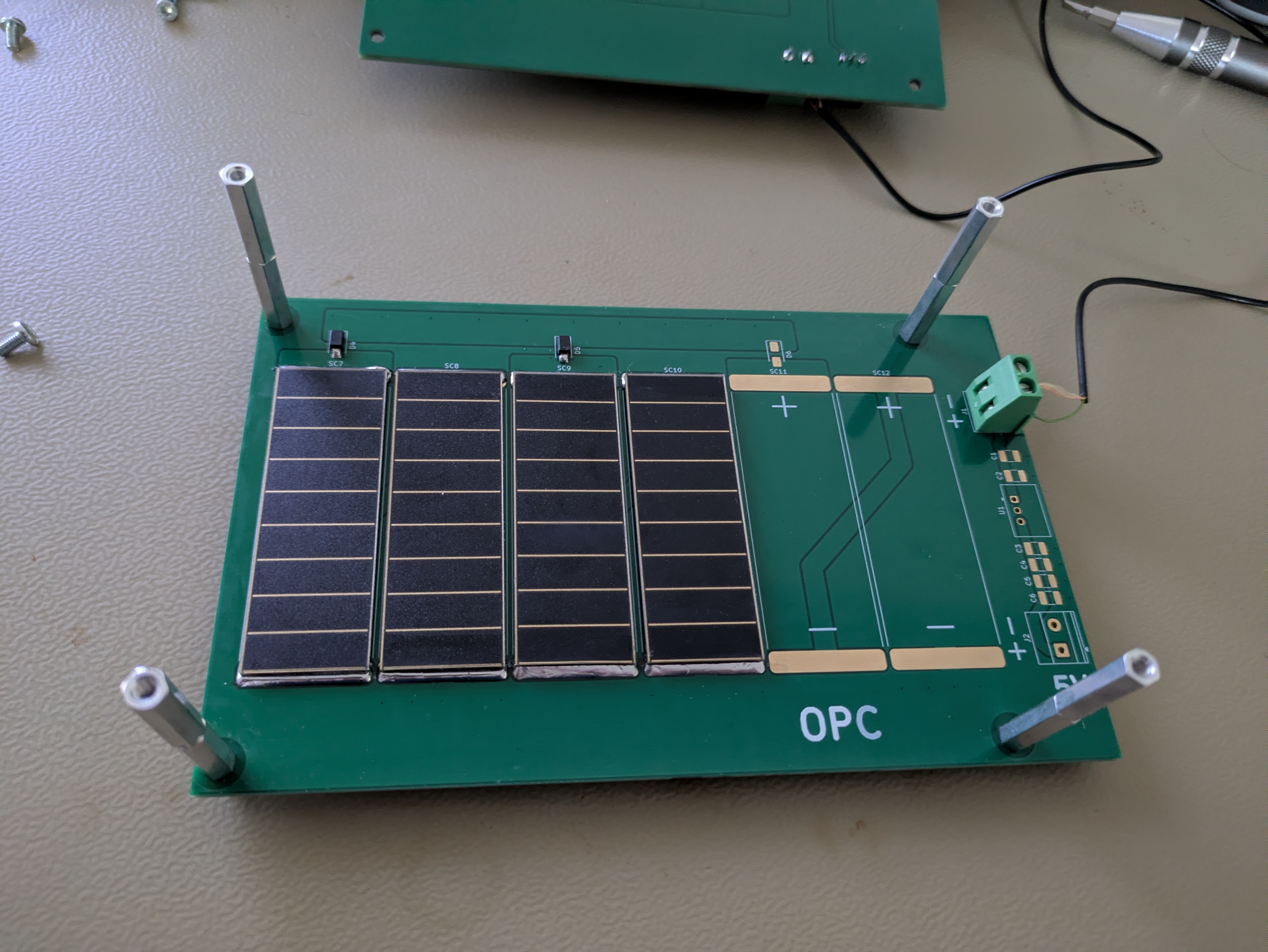
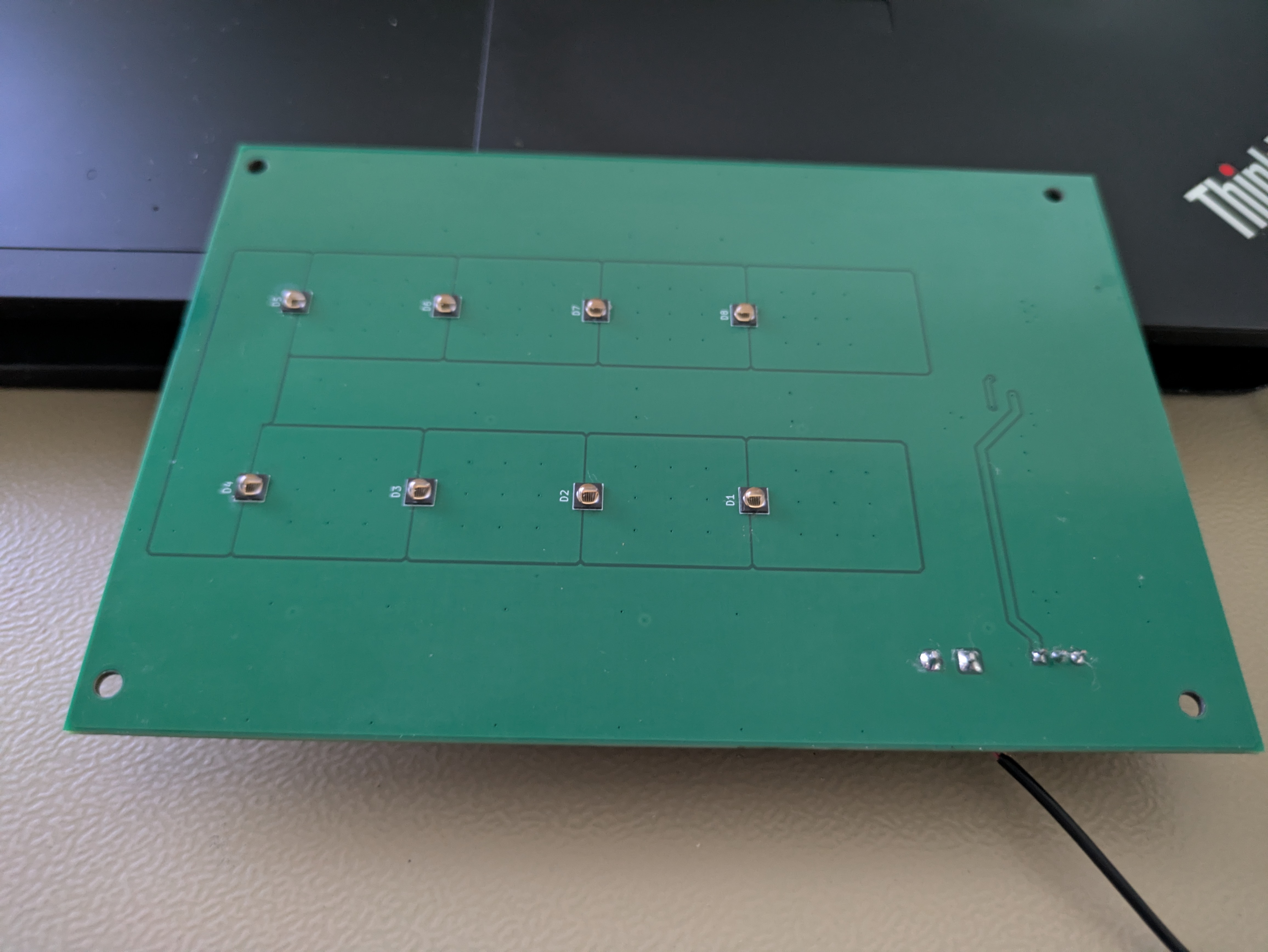
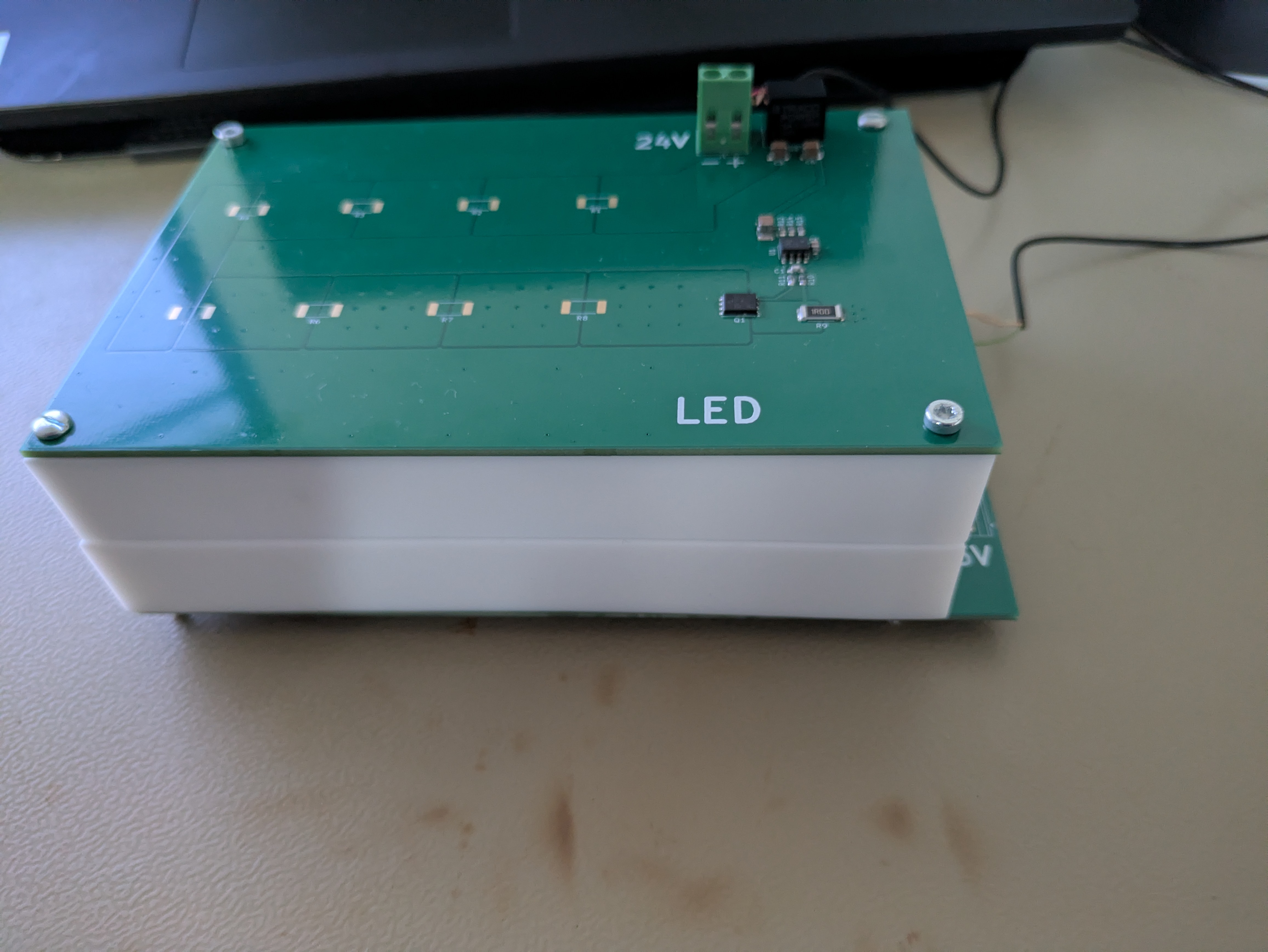
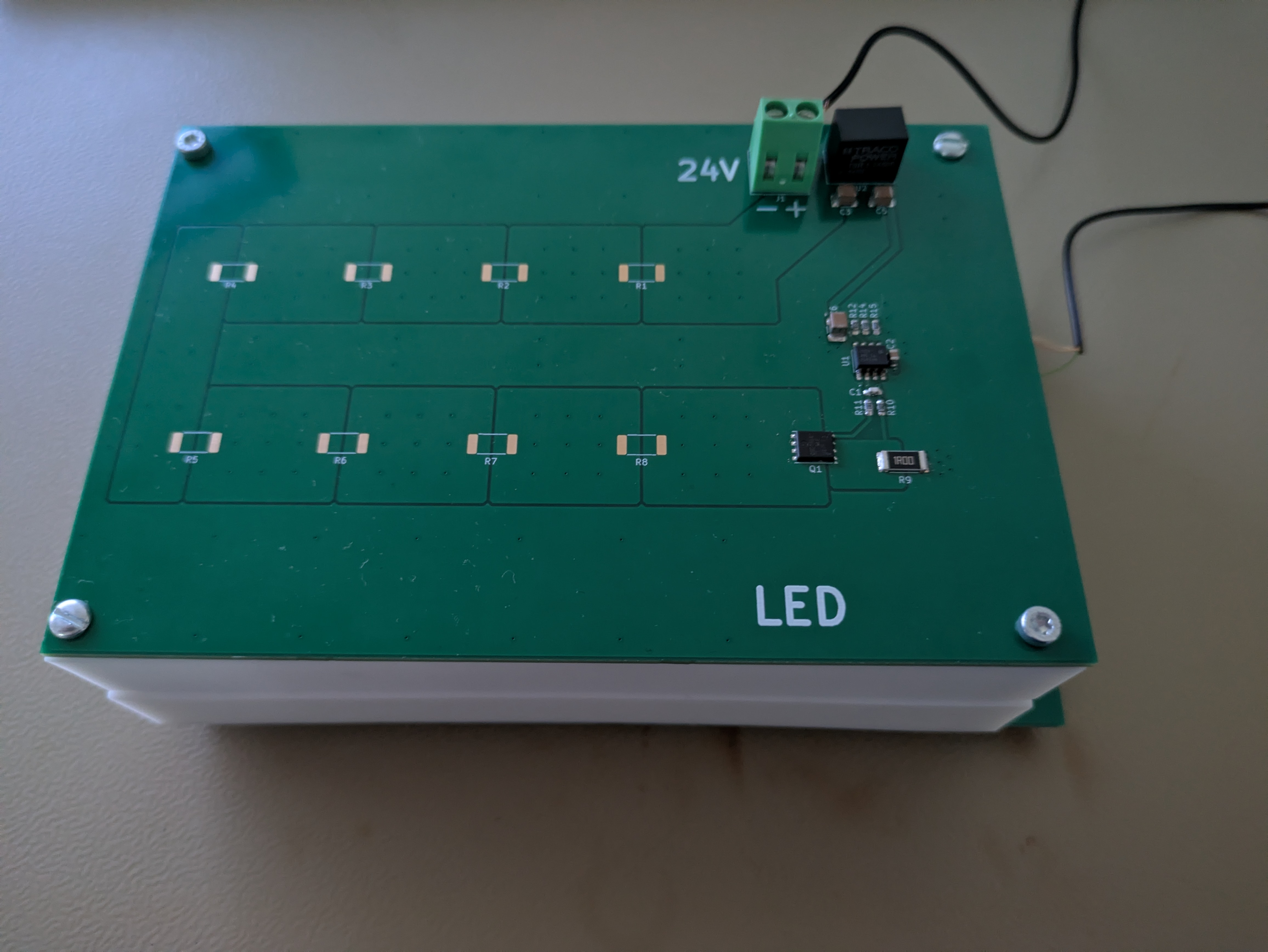
Used a 34410A DMM for voltage and current measurements. Measurement done for two distance between OPC-LED : 20 mm and 40 mm.
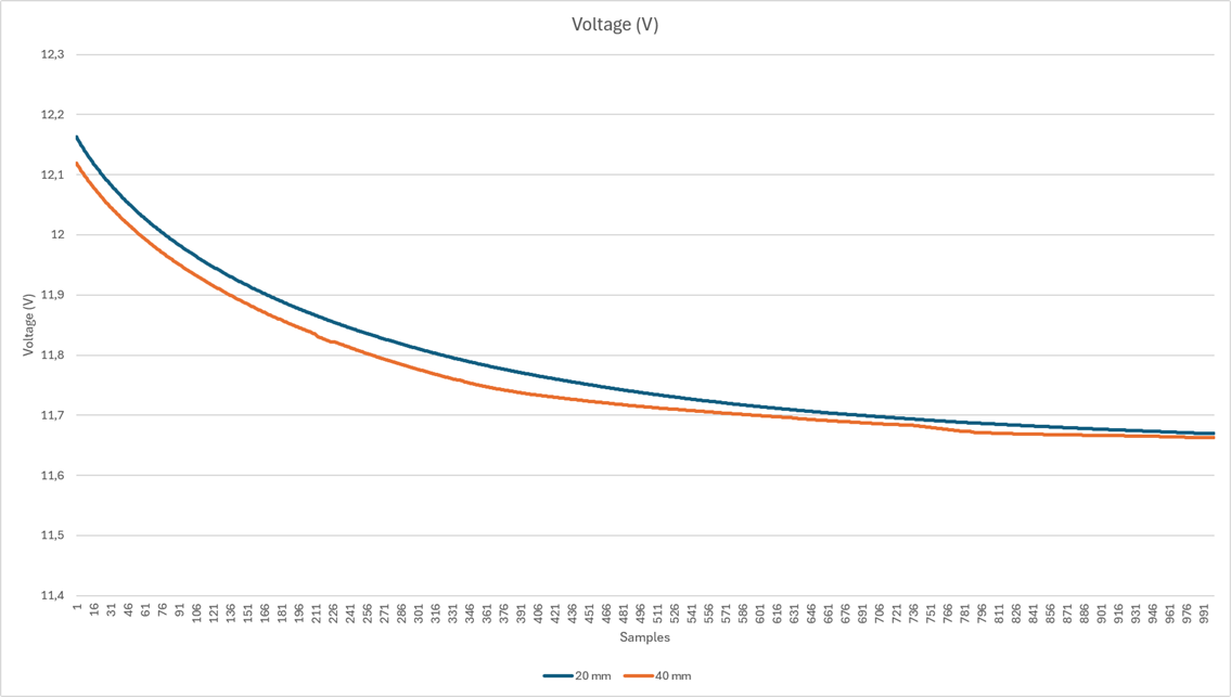 Figure 1: Open circuit voltage measurement. The LEDs were cooled with a fan. DMM: PLC 10, 1000 samples.
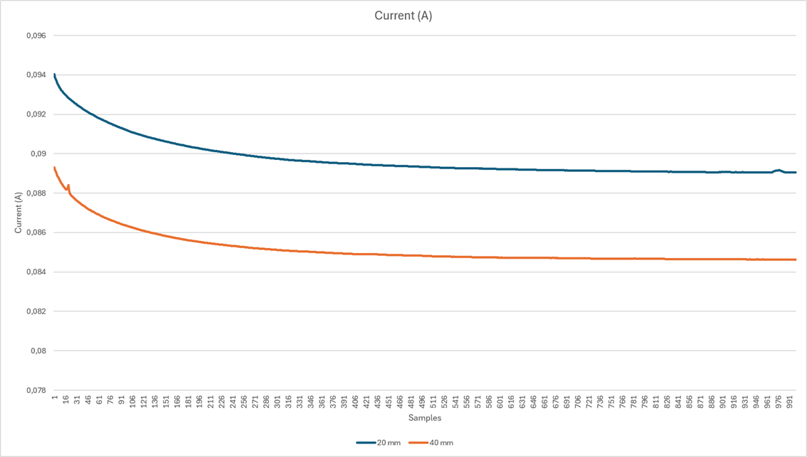 Figure 2: Short circuit current measurement. The LEDs were cooled with a fan. DMM: PLC 10, 1000 samples.
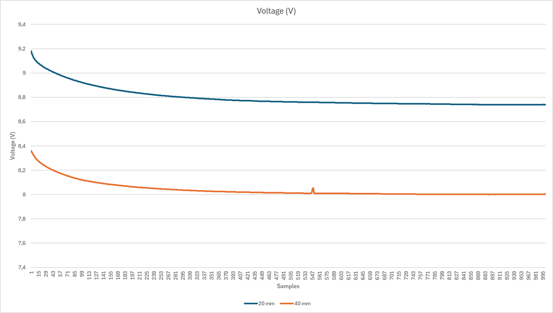 Figure 3: Voltage measurement with 110 ohm load. The LEDs were cooled with a fan. DMM: PLC 10, 1000 samples.
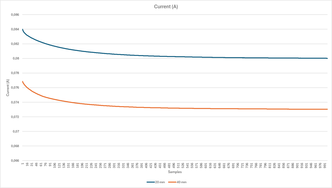 Figure 4: Current measurement with 110 ohm load. The LEDs were cooled with a fan. DMM: PLC 10, 1000 samples.
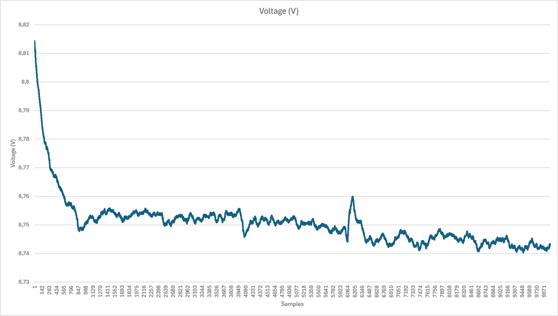 Figure 5: Voltage measurement with 110 ohm load. The LEDs and solar cells were cooled with a fan. DMM: PLC 10, 10000 samples. Distance 20 mm.
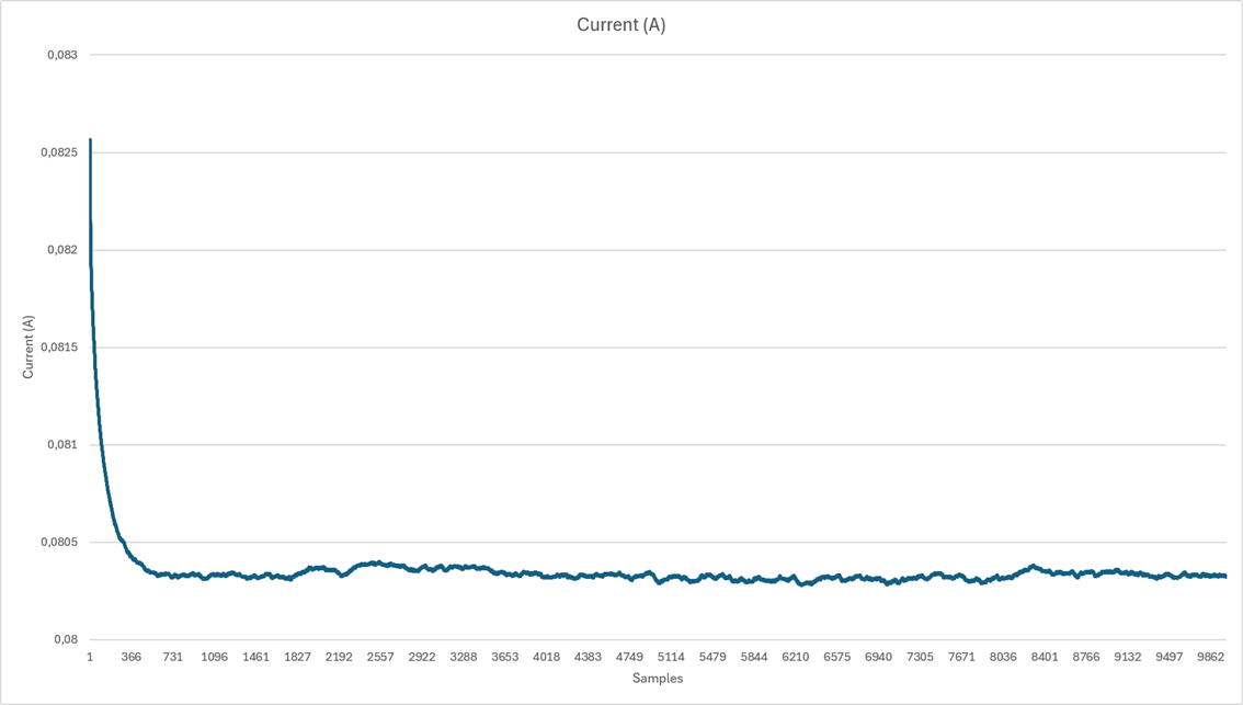 Figure 6: Current measurement with 110 ohm load. The LEDs and solar cells were cooled with a fan. DMM: PLC 10, 10000 samples. Distance 20 mm.
| Qty | Value | Footprint | References |
|---|---|---|---|
| 8 | 0R/5%/250mW | Resistor_SMD:R_2512_6332Metric_Pad1.40x3.35mm_HandSolder | R1, R2, R3, R4, R5, R6, R7, R8 |
| 8 | SFH 4715AS | OPC:SFH4715AS | D1, D2, D3, D4, D5, D6, D7, D8 |
| 4 | MountingHole | MountingHole:MountingHole_3.2mm_M3_DIN965 | H1, H2, H3, H4 |
| 3 | 22u/25V/X7R | Capacitor_SMD:C_1210_3225Metric_Pad1.33x2.70mm_HandSolder | C3, C5, C6 |
| 1 | 0.1u/100V/X7R | Capacitor_SMD:C_0603_1608Metric_Pad1.08x0.95mm_HandSolder | C2 |
| 1 | 100/1%/100mW | Resistor_SMD:R_0603_1608Metric_Pad0.98x0.95mm_HandSolder | R11 |
| 1 | 100k/0.1%/100mW | Resistor_SMD:R_0603_1608Metric_Pad0.98x0.95mm_HandSolder | R12 |
| 1 | 100p/100V/X7R | Capacitor_SMD:C_0603_1608Metric_Pad1.08x0.95mm_HandSolder | C1 |
| 1 | 110/0.1%/100mW | Resistor_SMD:R_0603_1608Metric_Pad0.98x0.95mm_HandSolder | R15 |
| 1 | 11k/0.1%/100mW | Resistor_SMD:R_0603_1608Metric_Pad0.98x0.95mm_HandSolder | R14 |
| 1 | 1715721 | TerminalBlock_Phoenix:TerminalBlock_Phoenix_MKDS-1,5-2_1x02_P5.00mm_Horizontal | J1 |
| 1 | 1k/1%/100mW | Resistor_SMD:R_0603_1608Metric_Pad0.98x0.95mm_HandSolder | R10 |
| 1 | CSD18501Q5A | Package_TO_SOT_SMD:TDSON-8-1 | Q1 |
| 1 | OPA192IDR | Package_SO:SOIC-8_3.9x4.9mm_P1.27mm | U1 |
| 1 | RNCL2512FT1R00 | Resistor_SMD:R_2512_6332Metric_Pad1.40x3.35mm_HandSolder | R9 |
| 1 | TSR1-2450E | Converter_DCDC:Converter_DCDC_TRACO_TSR1-xxxxE_THT | U2 |
It measures 148 × 100 mm and has 2 copper layers, 1.6 mm thick.
35 parts, built around the TSR 1-2450E and CSD18501Q5A. The full list of its parts is on this page, with links to each part's symbol and footprint where PCBKit's library has them.
From the BehrensG/PMOPC repository on GitHub, at the commit this page was made from: the board is LED/LED.kicad_pcb and its schematic LED/LED.kicad_sch. PCBKit opens the board in the browser, with nothing to install.
Its repository states no licence, so its author keeps all rights: ask BehrensG before reusing the design.


Ayan-nova/Design-of-a-Raspberry-PICO-Iot-Device-on-4-Layer-PCB-Design-With-Sensor-And-More
Design a Raspberry Pi Pico W-based Industrial IoT Gateway and Edge Controller using Kicad software.

baloghr/usonic
KiCad 9 project gp2026 (hardware revision 1.01): schematic, PCB, custom footprints (Library.pretty) and 3D models (packages3D).

ismailEngineer/omniwheel-robot
a small protoype to educate the control system of 3 OmniWheel Robot


Unimakers/CDR-2027
Ce repo est un site de documentation réalisé par l'équipe des première et deusième années pré-ingénieur de l'école Unilasalle-Amiens, membre de l'association de robotique Unimaker, dans le cadre de leur participation à…

