4 layers99.9 × 99.8 mm
Workbench
crgarcia12/electronics-workbench-controller
PCB board to control my electronics workbench
70 parts

 becem0/esp32-giant-chronometer
?? Giant 6-digit 7-segment race chronometer powered by ESP32, 24V COB LED strips, custom KiCad 10 PCB, and SIM800L GSM telemetry.
Stage chrono is an open-source printed circuit board by becem0, from the becem0/esp32-giant-chronometer repository on GitHub, published under the MIT licence. It is a 2-layer board of 131 × 90 mm with 38 parts on 141 nets, routed with 673 tracks and 4 vias.
It is built around the ESP32-DEVKITC-VE, 74HC595 and ULN2803A, with the MC001002 among its other parts. Its parts include 13 ICs, 8 capacitors, 8 connectors, 1 resistor and 1 diode. It belongs with the lEDs and displays boards and the ESP32 boards of this library.





 [blocked]
 [blocked]
An end-to-end industrial-grade embedded system featuring a 6-digit giant 7-segment display driven by high-lumen 24V COB LED strips, a custom modular KiCad 10 PCB, an ESP32-WROVER-E dual-core controller hosting an asynchronous real-time Web dashboard, and SIM800L GSM cellular telemetry.
Designed, developed, and fabricated by Bacem AMEUR (National Engineering School of Monastir - ENIM) during an engineering internship at Chrono Sports Events.
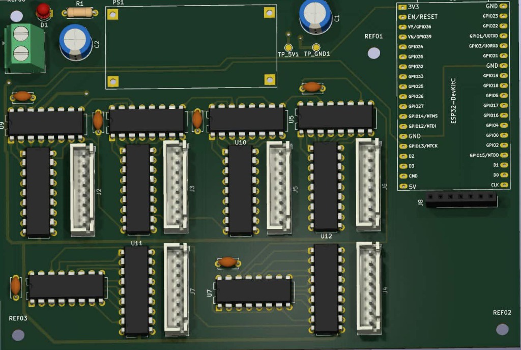
Figure 1: Photorealistic 3D CAD render of the assembled CHRONO_01 board in KiCad 10.
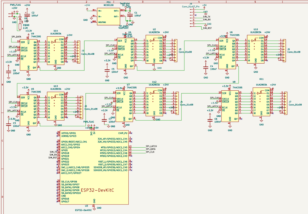
Figure 2: Complete electrical schematic (ESP32, 74HC595 cascade, ULN2803A drivers, LM2596 power regulation).
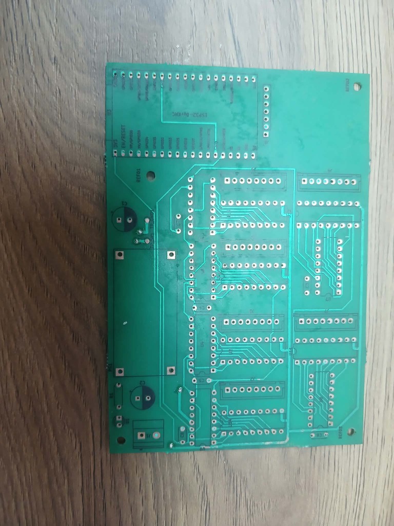
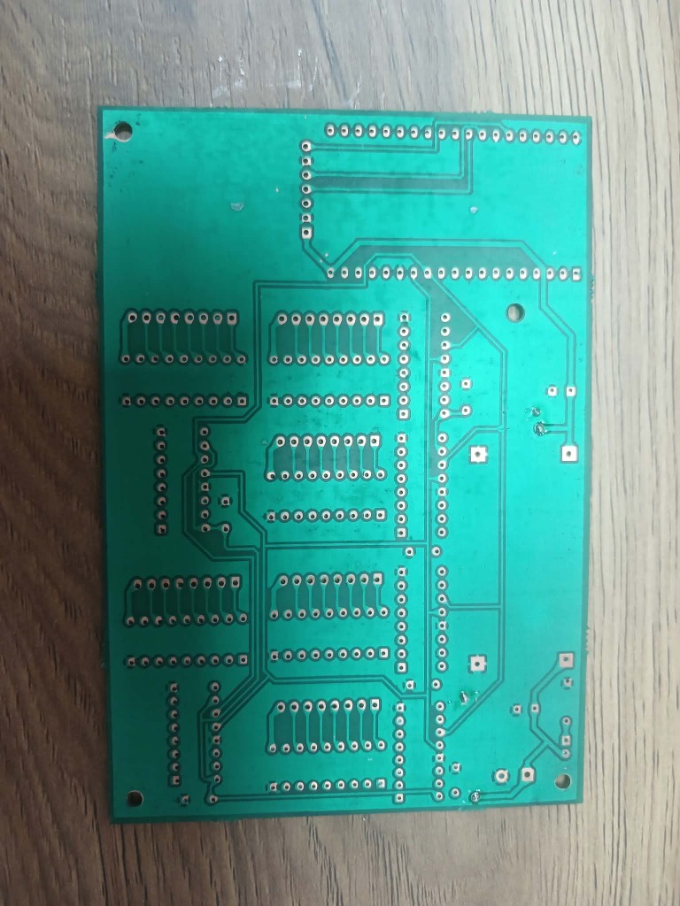
Figure 3: Double-sided physical PCB fabricated via chemical etching (Left: Component side F.Cu, Right: Solder side B.Cu).
HH:MM:SS) using high-density 24V COB LED strips for uniform, neon-like illumination without individual LED hotspots.SSID: CHRONO_01) and serves an asynchronous HTML5/CSS3/JavaScript dark-mode web application via ESPAsyncWebServer.74HC595 serial shift registers interfaced with 6 ULN2803A Darlington sink arrays, controlling 42 independent 24V segments at up to $500,\text{mA}$ per channel.SIM800L cellular transceiver with a customized $1000,\mu\text{F}$ low-ESR reservoir network to absorb 2.0A TDMA RF burst current drops. ┌─────────────────────────────────────────────────────────────────────────────┐
│ MAIN POWER SUPPLY │
│ (230V AC ──> 24V DC / 2.5A SMPS) │
└──────────────────────┬────────────────────────────────┬─────────────────────┘
│ (+24V Power Bus) │ (+24V Input)
▼ ▼
┌─────────────────────────────────┐ ┌──────────────────────────────┐
│ 42x 24V COB LED SEGMENTS │ │ LM2596 BUCK REGULATOR │
│ (6 Digits: A, B, C, D, E, F, G│ │ (24V DC ──> 5.0V / 4.1V) │
│ Common Anode Configuration) │ └──────────────┬───────────────┘
└────────────────▲────────────────┘ │
│ Sinking Grounds (x42) │
┌────────────────┴────────────────┐ ▼
│ 6x ULN2803A DARLINGTON │ ┌───────────────┐
│ TRANSISTOR ARRAYS │◄── 5V ──────┤ ESP32-WROVER │
└────────────────▲────────────────┘ │ DUAL-CORE │
│ 8-bit Parallel Out (x6) │ (Soft-AP Web │
┌────────────────┴────────────────┐ │ Server + │
│ 6x 74HC595 SERIAL │◄── SPI ─────┤ FreeRTOS) │
│ SHIFT REGISTERS │ (DATA/CLK/ └───────┬───────┘
└─────────────────────────────────┘ LATCH) │ UART (TX2/RX2)
▼
┌───────────────┐
│ SIM800L GSM │
│ (+1000uF Cap) │
└───────────────┘Driving 42 discrete LED segments using only 3 GPIO pins from the ESP32:
74HC595 Shift Registers: Cascaded in series. The serial frame ($6 \times 8 = 48,\text{bits}$) is clocked via high-speed SPI in less than $5,\mu\text{s}$.ULN2803A Darlington Sink Drivers: 8 open-collector channels with integrated clamp diodes per IC. Each output can sink up to $500,\text{mA}$ under $24,\text{V}$, perfectly matching the common-anode COB LED segments. ESP32 GPIO ────> 74HC595 (Qn) ───[2.7kΩ]───> ULN2803A (Base) ───> Sinks (-24V) to GND
▲
+24V Rail ───[LED Strip]─┘The GSM module consumes up to $I_{\text{peak}} = 2.0,\text{A}$ in $577,\mu\text{s}$ bursts. Without adequate capacitive reservoir sizing, the voltage droops below $3.7,\text{V}$, causing brownout resets.
The required charge buffer is sized according to: $$C_1 = \frac{I_{\text{peak}} \cdot \Delta t}{\Delta V_{\text{max}}} = \frac{2.0,\text{A} \times 577,\mu\text{s}}{0.4,\text{V}} \approx 2885,\mu\text{F}$$
Accounting for active source replenishment from the LM2596 buck converter, an effective capacitor of $1000,\mu\text{F}$ / 16V low-ESR in parallel with a $100,\text{nF}$ ceramic decoupling capacitor is placed directly at the SIM800L power pins.
To support artisan local PCB chemical etching without plated through-holes (NPTH):
The firmware is written in Arduino C++ utilizing ESP32 FreeRTOS multitasking:
| Task | Core Assigned | Priority | Execution Interval | Role |
|---|---|---|---|---|
WebNetworkTask | Core 0 | Priority 1 | Asynchronous | Handles Wi-Fi Soft-AP client connections, REST endpoints (/api/start, /api/pause, /api/reset, /api/set), and serves HTML5 assets from SPIFFS/Flash. |
ChronometerEngine | Core 1 | Priority 3 | $1.00,\text{ms}$ deterministic | Hardware timer tick accumulation, 7-segment digit lookup encoding, SPI shifting, and non-blocking SIM800L AT command parsing. |
The responsive dark-theme dashboard runs entirely embedded within the ESP32 SPIFFS memory:
CHRONO_01 (192.168.4.1).├── .gitignore
├── LICENSE
├── README.md
├── firmware/
│ ├── ChronoServer/
│ │ ├── ChronoServer.ino # Main dual-core ESP32 firmware
│ │ └── index.html # Embedded HTML5/CSS3/JS dashboard
│ └── tests/
│ ├── test_blink_esp32.ino # GPIO & RTC validation test
│ └── test_sim800l_at.ino # Hardware UART GSM pass-through test
├── hardware/
│ ├── kicad/ # KiCad 10 schematics (.kicad_sch) and PCB (.kicad_pcb)
│ ├── gerbers/ # Production Gerber and Excellon drill files
│ ├── schematics/
│ │ └── pinout_reference.md # Pinout table for JST & shift registers
│ ├── bom/
│ │ └── bill_of_materials.md # Detailed BOM and supplier breakdown
│ └── mechanical/
│ └── chassis_assembly.md # Chassis drilling, baffles, and wiring guide
└── docs/
├── Journal stage 2026.pdf # 30-day chronological internship journal
├── rapport_stage_2026.pdf # Compiled official internship engineering report
├── stage_chrono_presentation.pdf # Oral defense slide deck
└── report/
├── rapport_stage_bacem_ameur.tex # LaTeX source code
└── figures/ # High-resolution schematics, 3D renders & photos| Category | Key Items | Cost (TND) | Approx. (€) |
|---|---|---|---|
| Processing & Telemetry | ESP32-WROVER-E + SIM800L GSM + LM2596 Buck | ~90 TND | ~€26 |
| Power Drivers & Logic | 6x 74HC595 + 6x ULN2803A + Tulip DIP sockets | ~60 TND | ~€18 |
| Display & Illumination | 24V COB LED Strips (10m) + JST-XH harnesses | ~100 TND | ~€29 |
| Power Supply | S-60-24 SMPS (230V AC $\to$ 24V DC / 2.5A) | ~55 TND | ~€16 |
| Structure & Enclosure | Forex (PVC) backplate + Opal PMMA acrylic diffuser | ~80 TND | ~€24 |
| PCB & Consumables | Chemical double-sided etching (120 TND), solder, capacitors, wiring | ~355 TND | ~€105 |
| TOTAL PROJECT INVESTMENT | ~740 TND | ~€220 | |
| Commercial Equivalent Price | Turnkey 6-digit wireless race chronometers | 3,000 – 20,000 TND | €900 – €6,000 |
2.0.17 via Boards Manager).ESP32 Wrover Module (or ESP32 Dev Module)DIO (or QIO depending on flash vendor)40MHzEnabledDefault 4MB with spiffsESPAsyncWebServer & AsyncTCPfirmware/ChronoServer/ChronoServer.ino.CHRONO_0112345678http://192.168.4.1Bacem AMEUR
Electrical Engineering Student — National Engineering School of Monastir (ENIM)
This project is open-source and licensed under the MIT License.
| Qty | Value | Footprint | References |
|---|---|---|---|
| 6 | 100nF | Capacitor_THT:C_Disc_D5.0mm_W2.5mm_P5.00mm | C3, C4, C5, C6, C7, C8 |
| 6 | 74HC595 | Package_DIP:DIP-16_W7.62mm | U4, U5, U6, U7, U8, U9 |
| 6 | Conn_01x08 | Connector_JST:JST_XH_B8B-XH-A_1x08_P2.50mm_Vertical | J2, J3, J4, J5, J6, J7 |
| 6 | ULN2803A | Package_DIP:DIP-18_W7.62mm | U2, U10, U11, U12, U13, U14 |
| 4 | MountingHole_3.2mm_M3 | MountingHole:MountingHole_3.2mm_M3 | REF00, REF01, REF02, REF03 |
| 2 | 100uF | Capacitor_THT:CP_Radial_D8.0mm_P3.50mm | C1, C2 |
| 2 | TestPoint | TestPoint:TestPoint_Pad_D1.5mm | TP_5V1, TP_GND1 |
| 1 | 2.2K | Resistor_THT:R_Axial_DIN0207_L6.3mm_D2.5mm_P7.62mm_Horizontal | R1 |
| 1 | 24_IN | TerminalBlock_Phoenix:TerminalBlock_Phoenix_MKDS-1,5-2-5.08_1x02_P5.08mm_Horizontal | J1 |
| 1 | Conn_01x07_Pin | Connector_PinSocket_2.54mm:PinSocket_1x07_P2.54mm_Vertical | J8 |
| 1 | ESP32-DevKitC | Espressif:ESP32-DevKitC | U3 |
| 1 | LED | LED_THT:LED_D3.0mm | D1 |
| 1 | MC00100 | Espressif:CONV_MC00100 | PS1 |
It measures 131 × 90 mm and has 2 copper layers, 1.6 mm thick.
38 parts, built around the ESP32-DEVKITC-VE, 74HC595, ULN2803A and MC001002. The full list of its parts is on this page, with links to each part's symbol and footprint where PCBKit's library has them.
From the becem0/esp32-giant-chronometer repository on GitHub, at the commit this page was made from: the board is hardware/kicad/stage_chrono.kicad_pcb and its schematic hardware/kicad/stage_chrono.kicad_sch. PCBKit opens the board in the browser, with nothing to install.
Its repository publishes it under the MIT licence: you may reuse it on that licence's terms (keep the author's notice, and for a copyleft licence share your changes alike).
crgarcia12/electronics-workbench-controller
PCB board to control my electronics workbench

ramiroedson72-cloud/probador-bobinas-cop
Generador de disparos PWM para probar bobinas de encendido (COP). Un potenciómetro controla la frecuencia (10–200 Hz ≈ 300–6000 RPM en motor de 4 cilindros) y el firmware mantiene un dwell fijo de 3 ms recalculando el…

BryanFarras/Desain-Proyek-2
Autonomous Evacuation Rover (AER) is an integrated mobile robotics platform developed for autonomous exploration, mapping, hazard detection, and evacuation assistance in unknown or hazardous indoor environments.

domenicojbruno/IQP-Resonant-Space
An interactive "resonant wall" for a hallway. VL53L0X time-of-flight sensors detect when people cross a threshold, and a honeycomb of 13 hexagonal panels, each moved by a linear actuator, pulls back from and pushes out…

MSMRo/Fluorimetro_lowcost
La PCB Energy se usa para la alimentación del montaje, con una línea de 5 V para el Arduino Mega y una línea de 12 V para la iluminación.

mbuyukeskil/kicad-hardware-projects
KiCad PCB design projects, schematics, layouts, 3D views and manufacturing files.

SimonDaniel605/Development-of-a-Resistojet-Thruster
This project involves the development of a resistojet thruster for nanosatellite station-keeping.

OverInvented/Flippy
The code needed to build a mechanical 7-segment display that uses electromagnets to display characters