
2 layers40 × 30 mm

There are a few useful bits of information needed when working with these: - The part number of the immobiliser is located at the beginning of the eeprom from address 0x009 to 0x00E.
M7700 is an open-source printed circuit board by bdm310, from the bdm310/996-Immobilizer repository on GitHub. It is a 2-layer board of 32 × 42 mm with 3 parts on 35 nets, routed with 251 tracks and 26 vias.
Its parts include 2 ICs and 1 crystal.
This is a repository of information about the immobilizer on these 911/Boxster/Cayman cars. Part number of the unit here is 996-618-260-05.
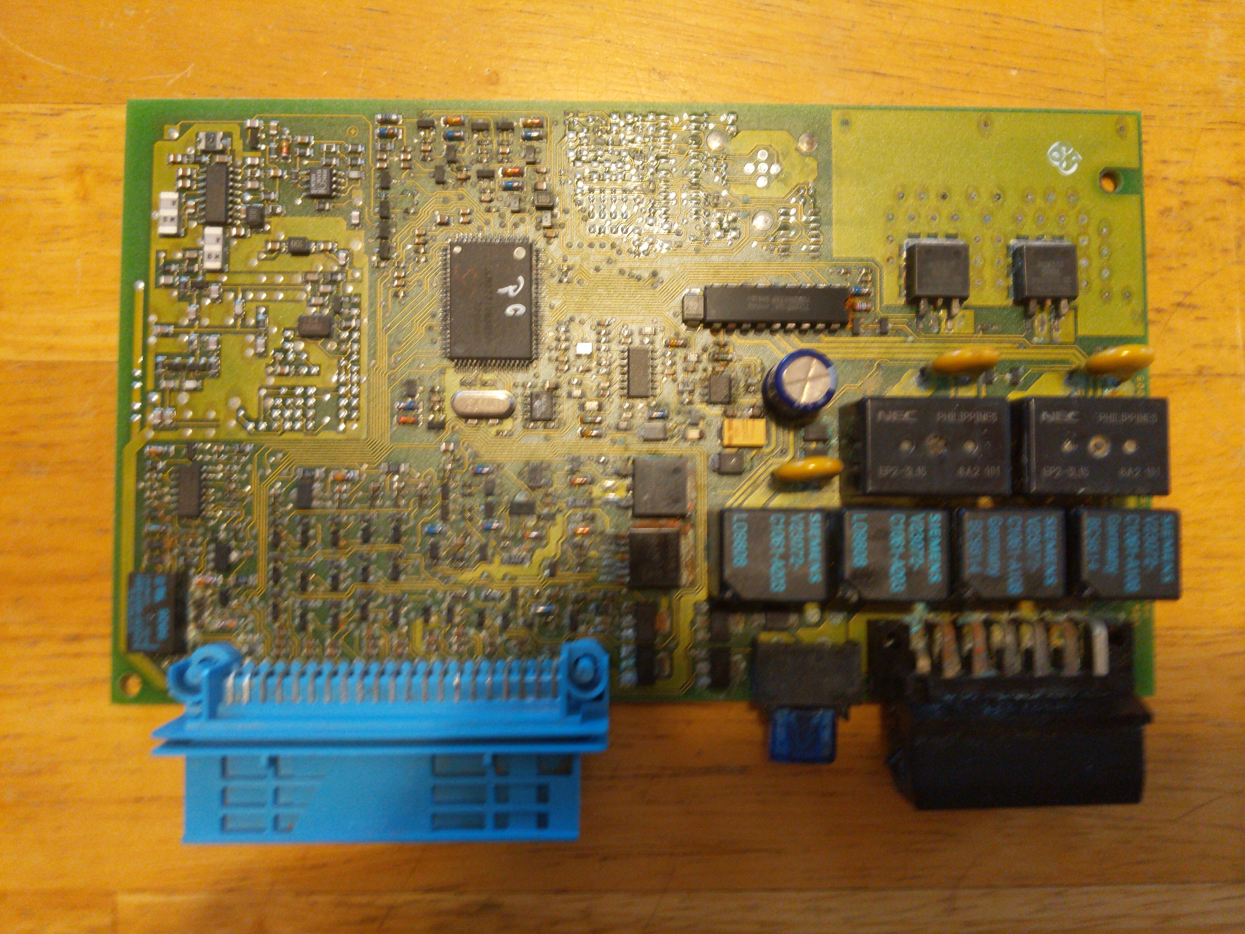
There are a few useful bits of information needed when working with these:
Using PIWIS to try various key learning codes:
So, you can get the learning code wrong at least 3 times with no lockout. Though, I am now noticing that the second attempt above actually had the right key and gave a different error than the first, definitely wrong, key attempt. Thus, there may be some time delay after a wrong attempt but thankfully no hard lockout.
The M534 and M535 are the same module but with 433MHz and 315MHz (USA) antennas for the keyfob, respectively.
There are at least two major versions of the M534/M535 module. The early cars use part 996.618.260.0x (where x varies according to minor revision) and the later cars use 996.618.262.0x. For boxsters, the changeover happend in 2001, when the electronic frunk release was implemented. There are a number of wiring differences between the major revisions which make them non-interchangable. It may be possible to repin certain wires to get basic functionaly, but I have not found anyone who tried this.
There's a 93LC66 EEPROM right next to the main processor. The processor has only ROM, so this EEPROM is the only possible place for configuration and state memory. Conveniently, this means you can easily clone a module or inspect the memory contents. I had no issues using an SOIC-8 chip clip and TL866 programmer in-circuit without removing the EEPROM or lifting any leads. If you intend to do any experimentation, it would be prudent to read out this chip beforehand. Since it's the only non-volatile memory, it seems safe to perform any PIWIS or other action while experimenting so long as you have a backup.
If you've got a water damaged module, you can probably get a cheap junkyard replacement and clone. That is, in fact, what started all this.
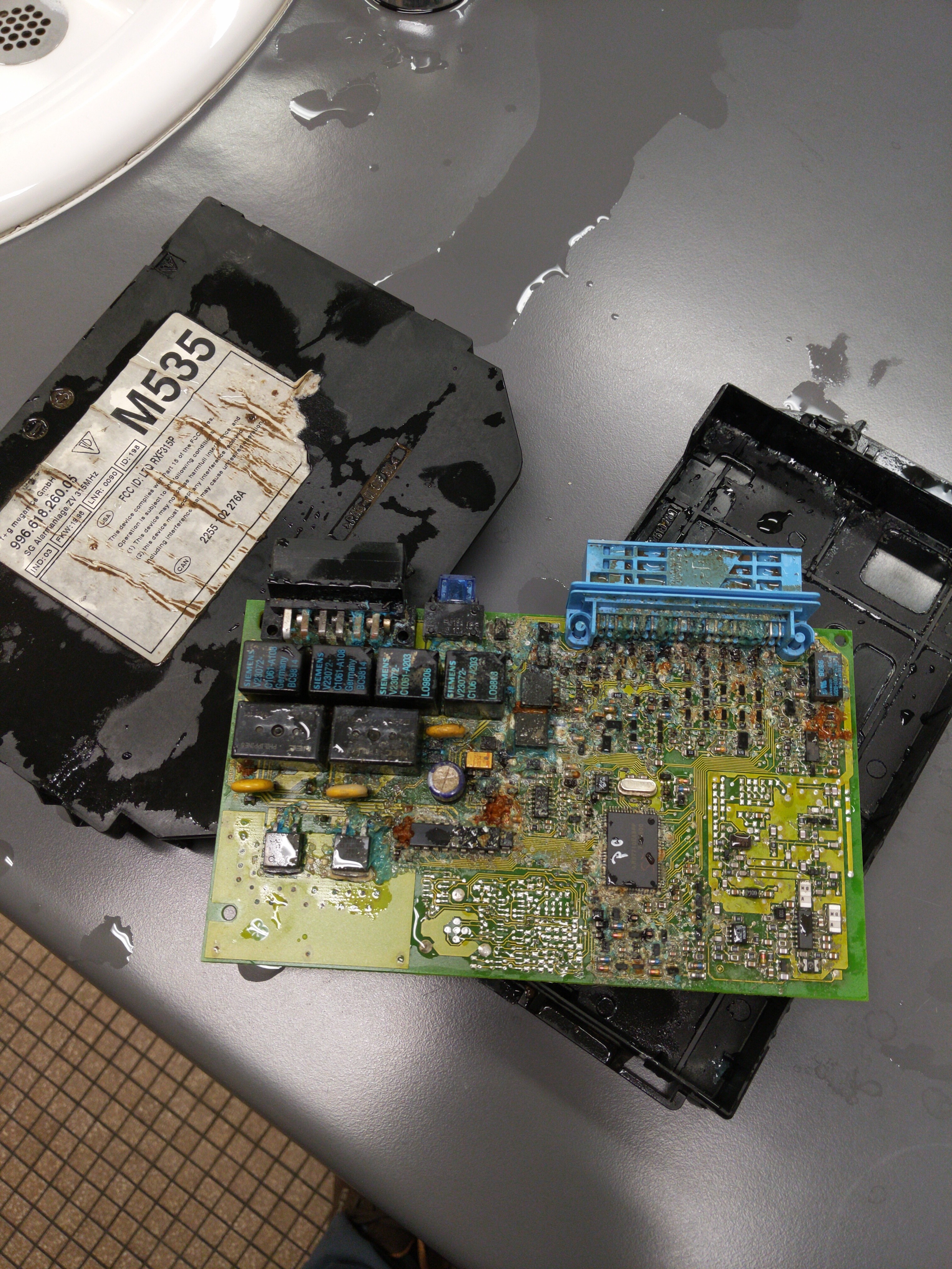
The ods spreadsheet details what I've learned about the detailed contents of this chip. There's a couple binary dumps here as well.
This module uses an M37710 microcontroller. Turns out that it looks just like an M5M27C101K when wired up a certain way, the M7700 folder has a PCB that does the right stuff. The binary hopefully will give up some secrets for programming key remotes without the original tags.
Every key head I've seen so far uses a Microchip product. I suspect the cipher is Keeloq but I cannot match the transmitted bitstream to any product datasheet I can find. Most notably, it's missing the seemingly ubiquitous synchronization preamble. You'll find LogicPro raw captures and a PulseView composite of a few captures in the reverse engineering folder.
| Qty | Value | Footprint | References |
|---|---|---|---|
| 1 | 27C010 | Package_DIP:DIP-32_W7.62mm | U1 |
| 1 | CXO_DIP8 | Oscillator:Oscillator_DIP-8 | X1 |
| 1 | ~ | M7700:QFP080-P-1420 | U2 |

hzeller/rpi-rgb-led-matrix
Controlling up to three chains of 64x64, 32x32, 16x32 or similar RGB LED displays using Raspberry Pi GPIO


atopile/atopile
Design circuit boards with code! ✨ Get software-like design reuse 🚀, validation, version control and collaboration in hardware; starting with electronics ⚡️


hackclub/sprig
🍃 Learn to code by making games in a JavaScript web-based game editor.
It measures 32 × 42 mm and has 2 copper layers, 1.6 mm thick.
3 parts. The full list of its parts is on this page, with links to each part's symbol and footprint where PCBKit's library has them.
From the bdm310/996-Immobilizer repository on GitHub, at the commit this page was made from: the board is M7700/M7700.kicad_pcb and its schematic M7700/M7700.kicad_sch. PCBKit opens the board in the browser, with nothing to install.
Its repository states no licence, so its author keeps all rights: ask bdm310 before reusing the design.