

2 layers110 × 48 mm
Jack pedal
GuitarML/GuitarPedalPCBs
Collection of KiCad circuit board designs for guitar pedals you can build yourself.
86 parts62MIT

 Batterhead221/Scream_Bean
This revision is intended to improve the original SCREAM_BEAN layout and move the board closer to a clean, buildable pedal PCB.
Scream bean rev b is an open-source printed circuit board by Batterhead221, from the Batterhead221/Scream_Bean repository on GitHub. It is a 4-layer board of 82.4 × 72.2 mm with 39 parts on 24 nets, routed with 207 tracks and 36 vias.
It is built around the NJM4558 and FS57003PLT2B2M2QE. Its parts include 13 capacitors, 8 resistors, 4 diodes, 3 connectors and 1 IC. It belongs with the audio and music boards of this library.
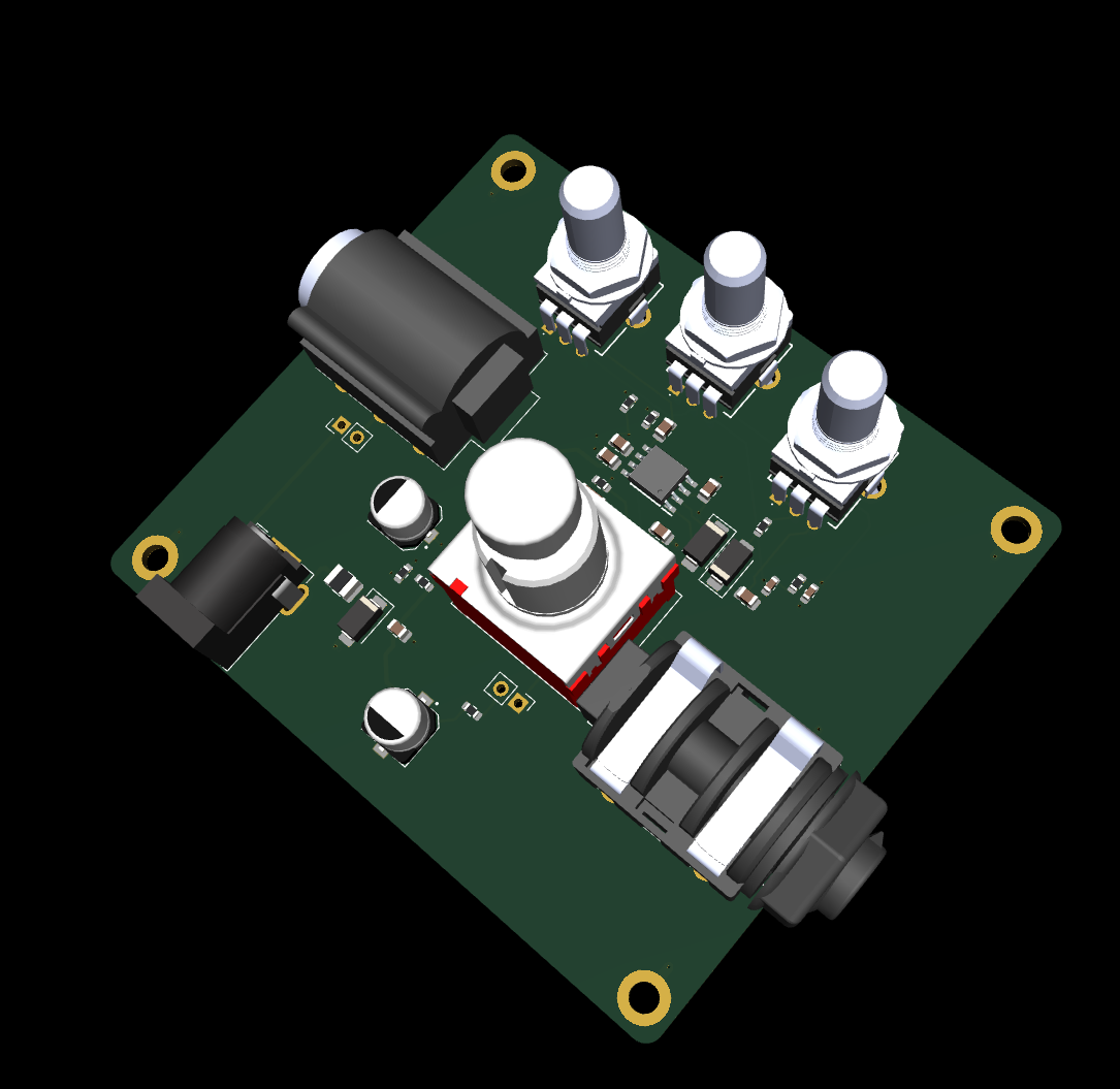
Project Status
This revision is intended to improve the original SCREAM_BEAN layout and move the board closer to a clean, buildable pedal PCB.
System Role
Guitar input ↓ input buffer / gain and clipping stages ↓ tone / level shaping ↓ output to amplifier or next pedal
Key Specs
Board role - Analog guitar drive/distortion pedal PCB Revision - Rev B Circuit style - Tube Screamer-inspired overdrive/distortion Sound target - Early-2000s pop-punk drive Power direction - 9V pedal supply / battery-style pedal ecosystem Controls - Drive / tone / level style pedal controls Audio path - Analog Board type - Stompbox effects pedal PCB
Main Features
Analog guitar input/output signal path Drive/clipping stage Tone-shaping network Output level control Pedal-style power input direction Compact board layout for enclosure use Silkscreen labels for bring-up and assembly Revision B layout improvements
SCREAM_BEAN_REV_B is inspired by the Tube Screamer topology, but it is not meant to be a component-perfect clone.
Design priorities:
Build a working analog drive circuit Learn op-amp gain/clipping behavior Shape the tone for pop-punk rhythm guitar Keep the board understandable and buildable Use layout practices that make audio debugging easier
Power Notes
Pedal power should be treated carefully.
pedal supply / battery input ↓ protection / filtering ↓ audio circuit power rail
Common first checks: no sound → check power, input/output jack wiring, IC orientation weak sound → check gain stage values and pot wiring harsh/fizzy → check clipping diode orientation and tone network hum/noise → check grounding and cable/enclosure wiring oscillation → check layout, power decoupling, and high-gain routing
Design Notes Keep audio input routing away from noisy power routing. Keep gain-stage feedback paths short. Keep power decoupling close to the IC. Use clear labels for pots, jacks, power, and switch wiring. Confirm enclosure fit before ordering a panelized or final version. Expect component value experiments while tuning the sound.
Repository Output Images
Expected image paths for GitHub README rendering:
Outputs/ IMG/ 3D-T.png 3D-B.png SCHEMATIC.png L1-SIG.png L2-GND.png
| Qty | Value | Footprint | References |
|---|---|---|---|
| 4 | MountingHole | MountingHole:MountingHole_3.2mm_M3_ISO14580_Pad_TopBottom | H1, H2, H3, H4 |
| 3 | 100K | RESISTOR:R_0603_1608Metric | R4, R7, R8 |
| 2 | 100n | CAPS:C_0805_2012Metric | C10, C11 |
| 2 | 100nF | CAPS:C_0805_2012Metric | C6, C8 |
| 2 | 10uF | CAPS:C_1206_3216Metric | C7, C9 |
| 2 | 1M | RESISTOR:R_0603_1608Metric | R1, R5 |
| 2 | 1N4148 | DIODE:D_SMA | D1, D2 |
| 2 | 1UF | CAPS:C_0805_2012Metric | C1, C4 |
| 2 | 4.7K | RESISTOR:R_0603_1608Metric | R2, R6 |
| 2 | 47u | CAPS:CAP_EEEFK1E470P | C12, C13 |
| 1 | 1K | RESISTOR:R_0603_1608Metric | R3 |
| 1 | 1N5817 | DIODE:D_SMA | D3 |
| 1 | 1uF | CAPS:C_0805_2012Metric | C2 |
| 1 | 220NF | CAPS:C_0603_1608Metric | C5 |
| 1 | 220n | CAPS:C_0603_1608Metric | C3 |
| 1 | 9V | PIN_HEADER:PinHeader_1x02_P2.54mm_Vertical | BT1 |
| 1 | 9V DC (CENTER -) | BARREL_JACK:BarrelJack_GCT_DCJ200-10-A_Horizontal | J1 |
| 1 | FS57003PLT2B2M2QE | STOMP:SW_FS57003PLT2B2M2QE | STOMP1 |
| 1 | GAIN_500K | POTS:RD901F4015R1B100K00DL1 | POT3 |
| 1 | LED | PIN_HEADER:PinHeader_1x02_P2.54mm_Vertical | D4 |
| 1 | NJM4558 | OP_AMP:SOIC127P680X200-8N | U1 |
| 1 | Polyfuse_Small | FUSE:Fuse_1210_3225Metric | F1 |
| 1 | TONE_20K | POTS:RD901F4015R1B100K00DL1 | POT2 |
| 1 | TRS | Audio:Jack_6.35mm_Neutrik_NMJ6HCD2_Horizontal | J4 |
| 1 | TS | Audio:Jack_6.35mm_Neutrik_NMJ4HCD2_Horizontal | J2 |
| 1 | VOLUME_100K | POTS:RD901F4015R1B100K00DL1 | POT4 |
It measures 82.4 × 72.2 mm and has 4 copper layers, 1.6 mm thick.
39 parts, built around the NJM4558 and FS57003PLT2B2M2QE. The full list of its parts is on this page, with links to each part's symbol and footprint where PCBKit's library has them.
From the Batterhead221/Scream_Bean repository on GitHub, at the commit this page was made from: the board is ECAD/scream_bean_rev_b.kicad_pcb and its schematic ECAD/scream_bean_rev_b.kicad_sch. PCBKit opens the board in the browser, with nothing to install.
Its repository states no licence, so its author keeps all rights: ask Batterhead221 before reusing the design.
GuitarML/GuitarPedalPCBs
Collection of KiCad circuit board designs for guitar pedals you can build yourself.


robertengineerr/linear_power_booster
Linear guitar signal booster with BJT amplification, true bypass switching, and power input protection.

cristianoag/wozblaster
Repository to host source files for the Wozblaster Reloaded


Jeff-Russ/Casio-HT-700-mods
A collection of instruction and schematics (in KiCAD with PCB designs) for modifying the Casio HT-700.

53175ddd/YM2203_DeveloperBoard
YAMAHA 製 FM 音源 IC YM2203 用の SPI インターフェース開発ボード